
Installation manual


6009-33 Installation Manual Setup – Other Parameters
13-2
13.7. Satellite Reference Mode
The ships gyro compass input to the ACU may be accurate and stable in static conditions and yet may NOT be
accurate or stable enough in some underway dynamic conditions. If there is no gyro compass or if the input is corrupt,
not stable or not consistently accurate the tracking errors will become large enough to cause the antenna to be mis-
pointed off satellite.
Satellite Reference Mode will uncouple the gyro reference from the azimuth rate sensor control loop. When operating
in Satellite Reference Mode changes in ships gyro reading will not directly affect the azimuth control loop. The
Pedestal Control Unit will stabilize the antenna based entirely on the azimuth rate sensor loop and the tracking
information from DishScan. This will keep the azimuth rate sensor position from eventually drifting away at a rate
faster than the tracking loop can correct by using the tracking errors to regulate the rate sensor bias.
Satellite Reference Mode can be used as a diagnostic mode to determine if tracking errors are caused by faulty gyro
inputs.
Satellite Reference Mode
• No Gyro Compass is available
MUST be used when:
• Frequent or constant ACU Error Code 0001 (Gyro Compass has failed)
• Gyro Compass output is NMEA heading
• Flux Gate Compass is being used
• GPS Satellite Compass is being used
To view, or change, the Satellite Reference Mode status, select the SAT REF remote parameter:
1. Press the RIGHT arrow, then press the UP arrow and last press the ENTER key to turn Satellite Reference Mode
ON.
2. Press the RIGHT arrow, then press the DOWN arrow and last press the ENTER key to turn Satellite Reference
Mode OFF.
If you change this remote parameter, you must save the change using REMOTE PARAMETERS.
13.8. REMOTE PARAMETERS
Allows any remote parameters that have been changed (via Remote Command or Remote Tilt) to be saved. Any
REMOTE changes must be saved to NVRAM in the PCU, or they will be lost when power to the antenna is cycled or
remote reset command is issued. Press RIGHT arrow and then press ENTER to save the parameters in the remote PCU's
NVRAM. A “Parameters Saved” message will be displayed.
13.9. Configuring the COMM IF ports of the DAC-2202 ACU
The Monitor and Control (M&C J3) port allows external control from a PC using a communications program such as
Sea Tel’s ProgTerm or DacRemP via a straight 9 wire serial cable. This Port is used in conjunction with a diagnostic
software connection to configure all communications settings, and/or for an Authorized Sea Tel Dealer to perform
software uploads to the PCU, ACU Main PCB, and DVB Receiver.
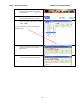
The Ethernet Port allows use of a LAN connection to login into the ACU’s internal webpage’s to view or change system
parameters using a web browser such as Internet Explorer or Mozilla Firefox. This 10BaseT Ethernet Port has a
configurable static IP address with 2 TCP/IP connections for diagnostic software connections and a UPD Port for an
Authorized Sea Tel Dealer to perform a software upload to the Comm IF Module.
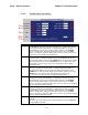
The NMEA J2 Port allows 2 simultaneous NMEA-0183 connections on the same DB9 connector, defined as NMEA A
and NMEA B. Both NMEA A (J2-Pin1 Rx+ and J2-Pin3 Tx-) and NMEA B (J2-Pin7 Rxe+ and J2-8 Txe-) Ports have
selectable baud rates independent of each other. The following procedure describes the process of connecting the
ACU to your Laptop and configuring all Comm IF Properties.
Hardware/Software Requirements:
• Laptop/Desktop with an available Serial Com Port and ProgTerm Version 1.33 (Build 11.Mar.2007 or later). If
no DB9 Serial port is available use a USB to Serial Adapter or use IP version of ProgTerm. Standard Straight 9
wire serial cable (Sea Tel Part Number 120643-25 or equiv.)
• DAC2202 Antenna Control Unit
1. Turn Power off to ACU