
Installation manual


6009-33 Installation Manual Functional Testing
14-2
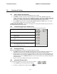
3. Press the RIGHT arrow key repeatedly and verify that the antenna physically moves up (CW) in
Azimuth and that the display accurately reflects that movement.
4. Press the LEFT arrow key repeatedly and verify that the antenna physically moves down (CCW) in
Azimuth and that the display accurately reflects that movement.
5. Press the UP arrow key repeatedly and verify that the antenna physically moves up (CW) in Elevation
and that the display accurately reflects that movement.
6. Press the DOWN arrow key repeatedly and verify that the antenna physically moves down (CCW) in
Elevation and that the display accurately reflects that movement.
14.5. Four Quadrant Test Tracking
A Four Quadrant Tracking Test is the best way to test tracking (regardless of which tracking mode is being used). This
tests each of the 4 quadrants (UP, DOWN, LEFT & RIGHT of peak signal AZ/EL pointing) to assure that the tracking
mode being used drives the dish back to peak satellite signal level. Note: Return to peak should take about the same
amount of time from each of the four quadrants.
1. Ensure tracking receiver parameters are set correctly and that system is on satellite with peak signal (AGC
above threshold).
2. Ensure tracking LED is off – If not press the TRACK key to toggle tracking off
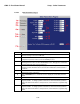
3. Press the NEXT arrow key a few times until Antenna menu is displayed
4. Note the current Azimuth and AGC values.
5. Press and hold the RIGHT arrow key to drive Azimuth down until displayed AGC drops 100 counts
(approx. 2-3 dB) (Do not drive antenna so far that AGC falls below threshold)
6. Press the TRACK key to re-enable tracking.
7. Monitor the Azimuth and AGC Values for the next 20-30 seconds.
8. Verify the Azimuth and AGC return to the values noted in step 4.
9. Verify the amount of time it took for tracking to bring AGC back to peak is within the specifications
** Nominal time to get back to peak is 8-30 seconds You should also be able to observe the DishScan tracking
decisions being carried out by ACU by viewing either a 2, 4, 6, or 8 in the bottom left-hand side of the
Azimuth Sub-menu display screen. A normal displayed response would be opposite than that of the axis
driven, i.e. for an antenna driven up (CW) is azimuth you would expect to see a majority of 4’s being
displayed indicating DishScan senses signal strength higher down in azimuth, therefore sending the Azimuth
Down command to PCU.
A flashing ‘2’ indicates an Elevation Down command
A flashing ‘8’ indicates an Elevation Up command
A flashing ‘4’ indicates an Azimuth Down (CCW) command
A flashing ‘6’ indicates an Azimuth Up (CW) command
A flashing ‘0’ indicates No antenna drive command
10. Repeat steps 2-9 driving antenna the other 3 directions, (Replace Step 5 with below steps as each direction is
tested)
11. Using the
LEFT arrow to drive antenna down (CCW) in Azimuth
12. Using the DOWN arrow key to drive antenna down in Elevation
13. Using the UP arrow key to drive antenna up in Elevation
If problems are encountered with tracking recovery refer to 123400_C DishScan document available on our dealer
support site.