
Installation manual

6009-33 Installation Manual Installation Troubleshooting
15-2
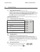
you MUST enter the beginning Heading value EVERY time you power-up the ACU, before you will be able to retarget
your desired satellite.
Verify that the SETUP PARAMETERS are set correctly (refer to the Setup section of this manual).
15.2.1.
This indicates no power to the internal electronics. Assure that the front panel Power switch is ON. Check
the AC line voltage on the Power Cord. Check the cables on the rear panel of the ACU to assure they are
properly connected. If AC Line voltage is Ok, one at a time disconnect (and check display status) the cables
plugged into J1 Gyro Compass, then J2 NMEA, then J3 M&C to see if one of these cables is shorting the ACU
Power. Call your dealer to report this failure and arrange for repair service.
ACU display is blank
15.2.2.
This indicates a problem in the Antenna Control coax cable or communications modems in the ACU and/or
Antenna PCU. Check the Antenna Control Cable connections at the J4 “Antenna” jack on the rear of the ACU
and at the antenna pedestal inside the radome. If the connections are good, call your dealer to report this
failure and arrange for repair service.
ACU Status displays "REMOTE NOT RESPONDING"
15.3. Troubleshooting Ships Gyro Compass problems
Ships Heading display does not follow ships movement and/or you are getting frequent or constant ERROR CODE
0001. Determine the type of gyro compass that is used on the ship, assure that the GYRO TYPE parameter is set
correctly (refer to the setup section of this manual) and then proceed to the step that lists the troubleshooting for the
correct type of Gyro Compass Signal.
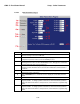
15.3.1.
1. Verify that the GYRO TYPE parameter is set correctly.
STEP-BY-STEP
2. Observe the ERROR LED on the FRONT panel. If it is illuminated, this indicates that an error was
detected in the Step-By-Step input. Press RESET on the front panel. If the ERROR LED illuminates
again, the problem is in the 4 connections to A, B, C and COMMON.
3. Check the connections to the Terminal Mounting Strip and to the ACU.
4. Measure the voltage between COMMON and A, B, and C. Each reading should either be near zero or
35 to 70 VDC. If all three are zero, check the repeater fuses. If some read negative and some read
positive or if one reads an intermediate values the COMMON terminal is not properly connected.
5. If the Ship - Heading display is different from the actual Gyro heading, access the Heading entry
menu and key in the correct heading value (refer to the operation Ship menu section). Note the
reading. After the ship has turned more than one degree, compare the new gyro heading with the
reading on the display, if it has moved in the opposite direction then reverse connections A and B.
Reset the ACU, put in the correct ship's heading again and verify that the display reading now
follows the Gyro heading.
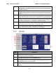
15.3.2.
Observe the ship's heading display on the ACU. Compare its movement with that of the ship. If it does not
move at all go to step 1. If it moves but in the wrong direction (even if it does not display the correct
heading) go to step 2. If it moves in the correct direction but does not display the correct heading go to step
3. The gyro compass connects to the Terminal Mounting Strip on TB3 R1, R2, S1, S2 and S3.
1:1 SYNCHRO
CAUTION - Electrical Shock Potentials exist on the Gyro
Compass output lines. Assure that the Gyro Compass output is
turned OFF when handling and connecting wiring to the
Terminal Mounting Strip.
1. The Ships Heading display does not change when the ship changes direction. Using a multimeter
read between R1 and R2. It should read 115 VAC. If it does not then a fuse is blown at the gyro
repeater or there is an open between the repeater and the ACU. Read between S1 and S2, S2 and
S3 and finally S3 and S1. They should all read between 0 and 90 VAC. The voltage level will change
as the ship turns. If one reading is very close to 0 volts wait until the ship has made a major change