
Installation manual


6009-33 Technical Specifications 6009-33 Installation Manual
17-3
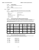
17.5. Pedestal Control Unit
The PCU Assembly contains 2 Printed Circuit Boards (PCBs). One is the main control board and the other is the Motor
Driver for the 3 Brushless DC Drive motors (AZ/EL/CL).
Connectors
Antenna Reflector 15 Pin D-Sub connector
Motor Interface 15 Pin D-Sub connector
M&C Interface SMA loop-through connectors
GPS Input BNC connector
Controls None
M&C Interface 9600 Baud 400MHz FSK
17.5.1.
Combined Signals (-1,-2)
400 MHz Unlimited Azimuth Modem/Multiplexer (3 Channel)
Pass-Thru 950-3650 MHz RX IF,
Injected 22Khz Tone
DC LNB Voltage Select
400 MHz Pedestal M&C
Connectors:
RX IF L-Band SMA female
Rotary Joint SMA female
RF / Ped M&C 9 pin D-Sub Connectors
Radio/Pedestal M&C Radio & Pedestal Control
Modulation FSK
Mode Full Duplex
Frequencies
BDE RF M&C TX = 447.5 Mhz +/-100 KHz
BDE Ped M&C TX = 452.5 Mhz +/-100 KHz
ADE RF M&C TX = 460.0 Mhz +/-100 KHz
ADE Ped M&C TX = 465.0 Mhz +/-100 KHz
Diagnostics LED Status Indicator for Power, Link communications and Self Test
Pedestal Interface RS-232/422