
Installation manual


DRAWINGS 6009-33 Installation Manual
18-1
18. DRAWINGS
The drawings listed below are provided as a part of this manual for use as a diagnostic reference.
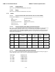
18.1. DAC-2202 Antenna Control Unit Drawings
Drawing Title
125411-1_J DAC-2202 w/ DVB Rackmount General Assembly 18-3
125411-3_J DAC-2202 w/ SCPC Rackmount General Assembly 18-5
18.2. 6009-33 Ku-Band Model Specific Drawings
Drawing Title
130454-101_A System, 6009-33 in 76” Radome 18-8
130288-101_A System, 6009-33 in 81” Radome 18-10
130357-3_A System Block Diagram, 6009-33 18-12
130028-1_B 76” Radome Assembly, Tuned 18-16
125749_C Installation Arrangement, 76” 18-19
130307-1_A 81” Radome Assembly, Tuned 18-20
122467-1_H Base Frame Assembly, 80.0 with A/C 18-22
125804_B Installation Arrangement, 81” 18-24
18.3. Series 09 General Drawings
Drawing Title
119478-5_C3 Cable Assembly, RJ-45 Serial (iDirect Modem Interface) 18-26
126877_B1 Harness Assembly, Comtech Modem Interface 18-27
121628-4_P Terminal Mounting Strip (iDirect Modem Interface) 18-28
121628-5_P Terminal Mounting Strip (Comtech Modem Interface) 18-30
129710-1_A Base Multiplexer Panel 18-32