CAUTION: This stabilized antenna system is designed to be used with transmit/receive equipment manufactured by others. Refer to the documentation supplied by the manufacturer which will describe potential hazards, including exposure to RF radiation, associated with the improper use of the transmit/receive equipment. Note that the transmit/receive equipment will operate independently of the stabilized antenna system.
These commodities, technology or software were exported from the United States in accordance with the Export Administration Regulations. Diversion contrary to U.S. law is prohibited. Sea Tel Marine Stabilized Antenna systems are manufactured in the United States of America. Sea Tel is an ISO 9001:2000 registered company. Certificate Number 19.2867 was issued August 12, 2005. Sea Tel was originally registered on November 09, 1998.
PRELIMINARY
PRELIMINARY
Introduction 1. 2. 3. 6009-33 Broadband At Sea INTRODUCTION .......................................................................................................................................................................................... 1-1 1.1. GENERAL SYSTEM DESCRIPTION.......................................................................................................................................................................1-1 1.2. PURPOSE...........................................
009-33 Broadband At Sea 5. 6. 7. Introduction 4.8. DEFAULT SETUP PARAMETERS ..........................................................................................................................................................................4-6 FUNCTIONAL TESTING .......................................................................................................................................................................... 5-1 5.1. ACU / ANTENNA SYSTEM CHECK ..............................
Introduction 8. 6009-33 Broadband At Sea 6009-33 TECHNICAL SPECIFICATIONS ..................................................................................................................................... 8-1 8.1. ANTENNA ASSEMBLY 6009 ..............................................................................................................................................................................8-1 8.2. SMW QUAD BAND LNB ......................................................................
6009-33 Broadband At Sea Introduction PRELIMINARY This Page Intentionally Left Blank viii
Introduction 1. 6009-33 Broadband At Sea Introduction WARNING: RF Radiation Hazard - This stabilized antenna system is designed to be used with transmit/receive equipment manufactured by others. Refer to the documentation supplied by the manufacturer which will describe potential hazards, including exposure to RF radiation, associated with the improper use of the transmit/receive equipment. Note that the transmit/receive equipment will operate independently of the stabilized antenna system.
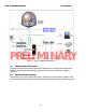
6009-33 Broadband At Sea Introduction PRELIMINARY Figure 1-1 Series 09 Simplified Block Diagram 1.4. General scope of this manual This manual describes the Sea Tel Series 09 Antenna (also called the Above Decks Equipment), its’ operation and installation. Refer to the manual provided with your Antenna Control Unit for its’ installation and operating instructions. 1.5. Quick Overview of contents The information in this manual is organized into chapters.
Operation 2. 6009-33 Broadband At Sea Operation Operation of your system is accomplished from the DAC-2202 Antenna Control Unit (ACU). Refer to the operation section of the DAC-2202 Antenna Control Unit manual. 2.1. System Power-up Turn the Power switch on rear panel of the Antenna Control Unit (ACU) ON. 2.2. Antenna Initialization A functional operation check can be made on the antenna stabilization system by observing its behavior during the 3 phases of initialization.
6009-33 Broadband At Sea 2.7. Operation Low Noise Block Converter Operation/Selection: There are three controls applicable to the LNB's installed on this system; 1 operational voltage selection, 2 operational tone control and selection of Co-Pol OR Cross-Pol Receive IF. Voltage and Tone, used to select the frequency band of the LNB, are supplied to the LNB which has been selected by the Co-Pol/Cross-Pol switch. DC voltage is supplied by the pedestal modem and Tone is supplied by the tone generator.
Installation 3. 6009-33 Broadband At Sea Installation Your antenna pedestal comes completely assembled in its radome. This section contains instructions for unpacking, final assembly and installation of the equipment. It is highly recommended that installation of the system be performed by trained technicians. 3.1. Unpacking and Inspection Exercise caution when unpacking the equipment. Carefully inspect the radome surface for evidence of shipping damage. 3.2.
6009-33 Broadband At Sea 3.4. Installation Installing the ADE The antenna pedestal is shipped completely assembled in its radome. WARNING: Hoisting with other than a webbed four-part sling may result in catastrophic crushing of the radome. Refer to the specifications and drawings for the fully assembled weight of your model Antenna/Radome and assure that equipment used to lift/hoist this system is rated accordingly.
Installation 6009-33 Broadband At Sea 7. 8. 3.4.2. 1. 2. 3. 4. 5. 6. 3.5. Bolt or weld the legs of the radome base frame directly to the ship's deck. If the deck is uneven or not level, weld clips to the deck and attach them to the legs of the radome base frame. When completed the radome base must be level. Disconnect the lifting sling from the four lifting eyes in the base of the radome.
6009-33 Broadband At Sea 3.6. Installation Below Decks Equipment. 3.6.1. System Configuration PRELIMINARY Figure 3-1 Series 09 Simplified Block Diagram 3.6.2. 1. 2. 3. 4. 5. 6. 7. 8. 3.6.3. Installing the Below Deck Equipment Install the ACU, Terminal Mounting Strip and Multiplexer Panel in your standard 19” Equipment Rack. Connect this equipment as shown in the System Block Diagram. Install and connect your other Below Decks Equipment (ie, Satellite Modem, telephone and computer equipment).
Installation 6009-33 Broadband At Sea 3.6.4. Terminal Mounting Strip Connections You will connect you Ships Gyro Compass input to the appropriate screw terminals on these strip. 3.6.5. Control Cable Connections The Serial Control Cable is connected from the Base Multiplexer to J4A on the DAC-2202. 3.6.6. NMEA GPS, Modem Lock & TX Inhibit Output Cable Connections The cable connection from TB 4 on the Terminal Mounting Strip to the Modem is pre-connected at the factory.
6009-33 Broadband At Sea Installation PRELIMINARY This Page Intentionally Left Blank 3-6
Set-up & Configuration 4. 6009-33 Broadband At Sea Set-up & Configuration The components in the system will have been configured with IP Addresses at the factory. The Front Title Page of this manual has a list of recorded IP address information, serial number information and Modem software version. In the paragraphs below you will verify the configuration of these components, which will also verify that each of them are communicating.
6009-33 Broadband At Sea Set-up & Configuration your transmit polarity and is much more accurate than you trying to optimize your receive polarity). Save your new TX POLARITY and POL OFFSET values (refer to Save New Parameters in your ACU manual). 4.4. Calibrating Relative Antenna Position (Home Flag Offset) During initialization, azimuth drives the CW antenna until the Home Switch is contacted, which “presets” the relative position counter to the value stored in the Home Flag Offset.
Set-up & Configuration 6009-33 Broadband At Sea If the antenna stopped before it got to the bow-line; When you initially target a satellite, the antenna will also stop prior to the satellite position, so you that will have to drive the Azimuth of the antenna UP to actually find the satellite. Using the same basic procedure as in the Optimizing Targeting paragraph, target the satellite and record the “Calculated” Azimuth position that the antenna was driven to.
6009-33 Broadband At Sea 4.4.2. Set-up & Configuration To Enter the HFO value: To enter the calculated HFO value, press & hold both LEFT and RIGHT arrows for six seconds to enter the parameter menu at the EL TRIM parameter window. Press DOWN arrow key numerous times (about 21) until you have selected the REMOTE COMMAND window. In the REMOTE COMMAND window, press the LEFT arrow key until you have underscored the left most character in the displayed value (ie the A in "A0000").
Set-up & Configuration 4.7. 6009-33 Broadband At Sea TRACK DISP This parameter set the selections that the user will see in the Tracking - Band Selection menu. Band Selection must be set to the appropriate selection for Tracking to operate properly. The Band selection controls the local logic output state of SW1 output terminal on the Terminal Mounting Strip PCB, the LNB voltage supplied by the pedestal modem, and the remote Aux Status (Co-Pol/Cross-Pol receive IF Coax switch) on the antenna pedestal.
6009-33 Broadband At Sea 4.8. Set-up & Configuration Default Setup Parameters The following table shows the factory default parameters for the DAC-2202 Antenna Control Unit interfaced to a Series 09 Antenna PCU. When the installation & setup of your system is finished you can record the “optimized” settings for your system in the “My Parameters” column.
Functional Testing 5. 6009-33 Broadband At Sea Functional Testing If not already ON, Turn ON the Power switch on the front panel of the ACU. 5.1. 1. 2. 3. 5.2. ACU / Antenna System Check Press RESET on the ACU front panel to initialize the system. Verify the display shows "SEA TEL INC MASTER" and the ACU software version number. Wait 10 seconds for the display to change to "SEA TEL INC - REMOTE" and the PCU software version number.
6009-33 Broadband At Sea 5.5. Functional Testing Four Quadrant Tracking Test This verifies that the antenna moves in the correct response to the keys, that Tracking is signaling correctly and that the Tracking commands are being carried out (antenna drives to peak). 1. Verify antenna is locked onto and tracking a satellite 2. Press the NEXT key several times to display the Antenna menu. 3. Note the current peak AGC value.
Functional Testing 5.7. 6009-33 Broadband At Sea Test Broadband Operation Open you Internet Browser and access several internet sites, email or other functions as you normally would. Operation should be the same as any equivalent service ashore. 5.8. Test Voice Over IP (VOIP) Operation If Voice Over IP equipment has been provided and services are available from you Internet Service Provider (ISP) you should verify that this equipment and service are functioning properly.
6009-33 Broadband At Sea Functional Testing PRELIMINARY This Page Intentionally Left Blank 5-4
Scheduled Preventive Maintenance 6. 6009-33 Broadband At Sea Scheduled Preventive Maintenance 6.1. Lowest Replaceable Unit Locations PRELIMINARY 6.2.
6009-33 Broadband At Sea 6.3. Scheduled Preventive Maintenance Monthly Operator Checks Description of Maintenance Operator Check 1.1.1. Test GPS Auto-Update 1.1.2. Heading Following 1.1.3. Check Tracking Receiver Settings 1.1.4. Four Quadrant Tracking Test 6.3.1. Test GPS Auto-Update This verifies that the GPS position information is automatically updating. 1. Press the NEXT key repeatedly to display the Ship menu. Press ENTER to access edit mode and view the current Latitude value. 2.
Scheduled Preventive Maintenance 3. 4. 6.4. 6009-33 Broadband At Sea Note the current peak ACG value. Press the Tracking key to toggle Tracking OFF, press the RIGHT arrow key repeatedly to move the antenna up in azimuth until AGC falls about 100 counts. Turn Tracking ON and verify that the antenna moves back down in azimuth and that the AGC rises to its’ previous high value. Note the current peak ACG value.
6009-33 Broadband At Sea Scheduled Preventive Maintenance c. If the damage is at the power ring, replace the power ring (refer to the “replacing the power ring” procedure in the Maintenance section of this chapter), 2. Inspect the Coaxes at the bracket on the radome base, through the pedestal base and at the dual channel rotary joint. Inspect both coaxes to assure that they are flexible and that the insulation is not brittle, chaffed or pinched. If any damage is found repair or replace the damaged coaxes.
Scheduled Preventive Maintenance 6009-33 Broadband At Sea e. Verify that the ends of the chain tensioner spring are properly hooked in the brackets and that the spring is not stretched. Rotate the chain tensioner away from chain to verify positive spring tension against chain. f. Using a screw driver or hook, disconnect one end of the spring and measure its length from inside of hook on one end to the inside of the hook on the other end.
6009-33 Broadband At Sea Scheduled Preventive Maintenance 13. Inspect the alignment of the belt through the motor drive sprocket and the driven sprocket. Misalignment will cause the belt to wear along its edges. 14. Inspect the belt teeth for damage. Look for teeth that have de-laminated from, or been completely torn off, of the belt. 15. Inspect the Elevation Motor and belt. Assure that there are no loose motor mounting hardware.
Scheduled Preventive Maintenance 4. 5. 6. 6009-33 Broadband At Sea Rotate the pedestal through full range of cross-level rotation (+/- 30 degrees). The antenna should rotate freely and easily with light finger pressure. Inspect all drive belts for wear (black dust on/under the area of the belt). Inspect AZ Drive chain. IF chain is beginning to show signs of rust or corrosion, apply a light coat of light duty oil to the chain. Wipe excess oil off to leave a light coating on the chain.
6009-33 Broadband At Sea Scheduled Preventive Maintenance PRELIMINARY This Page Intentionally Left Blank 6-8
Maintenance and Troubleshooting 7. 6009-33 Broadband At Sea Maintenance and Troubleshooting This section describes the theory of operation to aid in troubleshooting and adjustments of the antenna system. Also refer to the Troubleshooting section of your ACU manual for additional troubleshooting details. WARNING: Electrical Hazard – Dangerous AC Voltages exist in the Breaker Box and the Antenna Pedestal Power Supply.
6009-33 Broadband At Sea Maintenance and Troubleshooting OFF to balance the antenna. . Do NOT remove any of the drive belts. Balancing is accomplished by adding or removing balance trim weights at strategic locations to keep the antenna from falling forward/backward or side to side. The antenna system is not pendulous so 'balanced' is defined as the antenna remaining at rest when left in any position.
Maintenance and Troubleshooting 6009-33 Broadband At Sea • The Level display should decrease (plots below red line) as the antenna requires drive forward (Up in elevation) and increase (plots above red line) as the antenna requires drive back (Down in elevation). • Example: The antenna pictured in the screen capture below is imbalanced so that it is “Front Heavy”. The LV trace is plotting above the red line (indicating that drive CW is required to maintain the current elevation position).
6009-33 Broadband At Sea Maintenance and Troubleshooting Step 2: Press ‘ENTER’ key to go to Pol Offset window and verify setting is 0040. (If necessary use arrow keys to select appropriate digits and change accordingly) Step 3: Press ‘ENTER’ key to go to Tx Pol parameter and ensure it is set to 0002. (If necessary use arrow keys to select appropriate digits and change accordingly) Step 4: Press ‘NEXT’ key to select Antenna Window. Step 5: Press ‘ENTER’ key until ‘Pol xxxx’ is displayed.
Maintenance and Troubleshooting 6009-33 Broadband At Sea (Fig 1.1) (Fig 1.2) Step 10: On the ACU, push ‘ENTER’ key so that the cursor is not within the Pol display (Fig 1.3, failure to do this will result in display not changing). Rotate the Pol Pot gear manually until a count of 130 is achieved (Fig 1.3) Step 11: Reengage Pol Pot gear with the driven gear, while trying to maintain the 130 Pol Value set in step 10 and tighten the mounting plate screw loosened in step 9.
6009-33 Broadband At Sea 7.2.4. Maintenance and Troubleshooting To Reset/Reinitialize the Antenna: Pressing Reset on the ACU front panel does NOT cause a reset of the above decks equipment. To Re-initialize the antenna from the REMOTE COMMAND window on the ACU: 1. Using the LEFT/RIGHT and UP/DOWN arrow keys set the Remote Command value to "^0090" and press ENTER. This resets the PCU on the antenna.
Maintenance and Troubleshooting 7.2.6. 6009-33 Broadband At Sea Replacing the Rubber Bumpers Use Sea Tel replacement kit 129978 11. Using a 6mm wrench, loosen and remove all four of the rubber bumper assemblies. 12. Apply Loctite to the exposed threads of the four replacement rubber bumper assemblies. 13. Install and tighten the four replacement rubber bumper assemblies to torque spec. PRELIMINARY 7.2.7. Replacing the Flow Control Valves Use Sea Tel replacement kit 129976 1. 2.
6009-33 Broadband At Sea 3. 7.2.8. Maintenance and Troubleshooting Install the replacement flow control valves in the side of the pneumatic dampener. Replacing the Pneumatic Dampener Use Sea Tel replacement kit 129977 4. Using a 12mm wrench, loosen, remove and discard the top bolt of the pneumatic dampener assembly.
Maintenance and Troubleshooting 6009-33 Broadband At Sea 5. Loosen, remove and discard the bottom bolt of the pneumatic dampener assembly. 6. Discard the pneumatic dampener assembly. 7. Apply Loctite to the M12x40 and M12x55 bolts provided in the kit. Place a lock washer on each bolt. 8. Install the M12x55 bolt through the bottom of the replacement pneumatic dampener and into the threaded mounting.. 9.
6009-33 Broadband At Sea 7.3. Maintenance and Troubleshooting Pedestal Control Unit Configuration – Series 09 The PCU is designed to be used with a variety of antenna pedestal models. So, the PCU must be configured correctly for the model number of the antenna it is mounted on. The configuration information that is unique to each pedestal model is stored in a Non Volatile Random Access Memory (NVRAM) in the PCU enclosure.
Maintenance and Troubleshooting 7.4. 6009-33 Broadband At Sea Troubleshooting 7.4.1. RF Flow: Cross-Pol/Co-Pol switching and Quad Band LNBs Your antenna system has hardware components installed onto it to allow the operator a choice of providing either Co-Pol or Cross-Pol receive IF signal (in any of four frequency bands) to your satellite modem via the Tracking Band selection (refer to Chapter 5 for detailed setup information on this parameter or Chapter to for detailed operation information).
6009-33 Broadband At Sea Maintenance and Troubleshooting The output port of the coax switch is connected to the L-band port Pedestal M&C Mux, to provide Co-Pol or Cross-Pol LNB output, of the selected frequency band, through the receive channel of the rotary joint to below decks via the receive IF coax cable. There are three controls applicable to the LNB's installed on this system; 1 operational voltage selection, 2 operational tone control and selection of Co-Pol OR Cross-Pol Receive IF.
Maintenance and Troubleshooting 7.4.3. 6009-33 Broadband At Sea Troubleshooting using DacRemP While troubleshooting a Sea Tel 3-Axis Antenna System, you must classify the fault you are dealing with as a failure within one of 3 major system functions, Targeting, Stabilization, and Tracking. Should there be a failure with any one of these functions, your system will not operate properly. A few simple checks may help determine which fault (if any) that you are dealing with.
6009-33 Broadband At Sea Maintenance and Troubleshooting cable binding, or wind loading. If these forces cause the antenna to mis-point by more than 0.5° from the desired position the PCU will flag a “Stab Limit” error. • To view the position error, select the • This chart displays sensed axis errors via three traces, CL (Cross Level), LV (Elevation), and AZ (Azimuth), at a fixed 0.05º/ vertical division. • The normal trace average will plots it’s display ± 3 divisions from the red reference line.
Maintenance and Troubleshooting 6009-33 Broadband At Sea Elevation Axis physically moved CW. (reflector slightly pushed up) and then physically moved CCW. (reflector slightly pushed down.) At the end of chart recording shows • 7.4.5. DishScan Drive turned Off, notice the lack of accumulated IVC errors.
6009-33 Broadband At Sea 7.4.6. Maintenance and Troubleshooting Open Loop Motor Test The DacRemP Comm Diagnostics Window provides a means to enter in Remote Commands for driving each individual torque motor to test that motors functionality. By driving each axis and observing the resulting motion of the antenna, a coarse operational status of the motor and motor driver may be established.
Maintenance and Troubleshooting 6009-33 Broadband At Sea input is corrupt, not stable or not consistently accurate the tracking errors will become large enough to cause the antenna to be mis-pointed off satellite. Satellite Reference Mode will uncouple the gyro reference from the azimuth rate sensor control loop.
6009-33 Broadband At Sea 2. Maintenance and Troubleshooting Left mouse click on the icon. 3. Right mouse click on the icon. This will display a list box with the status of the above decks pedestal filtered into 3 sections. Items preceded with a check marks indicate a flagged status. See matrix below for further information on each state.
Maintenance and Troubleshooting 6009-33 Broadband At Sea PCU Status (Word 2) Az Target Indicates the antenna is currently targeting a pre-determined azimuth position Az Velocity **Not a valid state** Valid Heading (PCU) Indicates that the PCU has received and integrated the heading value from the ACU into the Azimuth Stabilization Loop. This is NOT an indication of a proper Heading integration into ACU. PCU Error Indicates that one or more errors have been reported by the above decks equipment.
6009-33 Broadband At Sea 2. Left mouse click on the icon. 3. Left Mouse click on the “?@ PCU GPS position, 1 min (1 Nm)” Maintenance and Troubleshooting PRELIMINARY 4. In the “Response” window verify proper GPS position to within 1 nautical mile of your current position.
Maintenance and Troubleshooting 6009-33 Broadband At Sea Furuno default value is in Japan at 34.4N 135.2E (@3444,N,13521,E,,_). After acquiring a good fix at Sea Tel the string is @3800,N,12202,W,A^ for our 38N 122W Latitude and Longitude position. The status character tells you the status of the GPS. “,” (Comma) = GPS has NOT acquired a proper fix, “N” = GPS fix is NOT valid “A” = GPS has acquired a valid fix.
6009-33 Broadband At Sea Maintenance and Troubleshooting PRELIMINARY This Page Intentionally Left Blank 7-22
6009-33 Technical Specifications 8. 6009-33 Broadband At Sea 6009-33 Technical Specifications The specifications of your 6006 antenna system are below. 8.1. Antenna Assembly 6009 The antenna assembly is comprised of the Dish, feed assembly and LNB. A variety of LNBs could be used, refer to LNB specification for the LNB that is provided with your system.: Reflector Size: Diameter – active area 1.5 M (60.
09-33 Broadband At Sea 8.3. TX Radio Package SSPBUC (Block Up-Converter) Co-Pol Diplexer Common Port (to feed) Transmit Output (from SSPB) Receive Output (to Co-Pol LNB) Co-Pol LNB 8.4. 6009-33 Technical Specifications NJRC 5017, 8 Watt SSPBUC DPX75K-002 WR-75 Flange, 10.70-14.5 GHz WR-75 Flange, 13.75-14.5 GHz WR-75 Flange, 10.70-12.
6009-33 Technical Specifications 8.5. 6009-33 Broadband At Sea Radome Assembly, 66” Type Material Size Tuned “A” sandwich Composite foam/laminate Diameter: Height: Hatch size Installed weight RF attenuation 1.76 M (69.35 inch) 1.76 M (69.40 inch ) 0.43 x 0.66 M (17 x 26 inch) MAX 600 lbs. (Including antenna pedestal). Less than 0.3 dB @ 10.7-12.75 GHz, dry Less than 0.3 @ 14.0-14.5 GHz, dry PRELIMINARY Withstand relative average winds up to 56 m/sec (125 mph) from any direction.
6009-33 Broadband At Sea 8.6. 6009-33 Technical Specifications Pedestal Control Unit The PCU Assembly contains 2 Printed Circuit Boards (PCBs). One is the main control board and the other is the Motor Driver for the 3 Brushless DC Drive motors (AZ/EL/CL). Connectors Antenna Reflector 15 Pin D-Sub connector Motor Interface 15 Pin D-Sub connector M&C Interface SMA loop-through connectors GPS Input BNC connector Controls None M&C Interface 9600 Baud 400MHz FSK 8.6.1.
6009-33 Technical Specifications 8.8.2. 6009-33 Broadband At Sea Chemically Active Substances Environmental Condition Sea Salt 8.8.3. Test Level 5 percent solution Mechanical Conditions Environmental Condition Systematic Vibration Amplitude Acceleration Frequency Range Test Level 5.0 millimeters 2.0 G (20 m/s2) 1Hz-150 Hz Shock (Transient Vibration) Response Spectrum Peak Accel., m/s2 Duration, ms Number of Cycles Directional Changes Shock (Bump) Peak Accel.
6009-33 Broadband At Sea 6009-33 Technical Specifications 8.10. Cables 8.10.1. Antenna Control Cable (Provided from ACU to the Base MUX) RS-422 Pedestal Interface Type Number of wires Wire Gauge Communications Parameters: Interface Protocol: Interface Connector: Shielded Twisted Pairs 4 24 AWG or larger 9600 Baud, 8 bits, No parity RS-422 DE-9P 8.10.2.
DRAWINGS 9. 6009-33 Broadband At Sea DRAWINGS The drawings listed below are provided as a part of this manual for use as a diagnostic reference. 9.1.
6009-33 Broadband At Sea DRAWINGS This Page Intentionally Left Blank PRELIMINARY 9-2
SINGLE LEVEL MFG BILL OF MATERIAL FIND QTY PART NO REV DESCRIPTION REFERENCE DESIGNATOR 1 1 EA 130342-1 A GENERAL ASS'Y, 6009-33 2 1 EA 130307-1 X1 RADOME ASS'Y, 81 INCH, WHITE, TUNED 3 1 EA 130291-1 X2 RADOME BASE ASS'Y, 80.8 STEEL, WITH A 4 0 EA 124167-X (REF ONLY) SSPB, KU-BAND, LBUC, CODA 5 0 EA 127386-X (REF ONLY) LNB, SMW, QUAD L.O.
PRELIMINARY
SINGLE LEVEL MFG BILL OF MATERIAL FIND QTY PART NO REV DESCRIPTION REFERENCE DESIGNATOR 1 1 EA 130342-1 A GENERAL ASS'Y, 6009-33 4 1 EA 125651-3 H FEED ASS'Y 6006KU, SMW LNB 5 2 EA 127386-X (REF ONLY) LNB, SMW, QUAD L.O.
SINGLE LEVEL MFG BILL OF MATERIAL FIND QTY 60 2 EA 115492-1 C1 ADAPTER, N(F)-SMA(F), W/FLANGE 61 1 EA 116466 D ROTARY JOINT, 4.5 GHz, DUAL COAX. 62 1 EA 128010-1 B RF COAX SWITCH ASS'Y, 75 OHM 70 1 EA 128059 B1 FILTER, TX REJECT, WR-75, 13.75-14.
SINGLE LEVEL MFG BILL OF MATERIAL FIND QTY PART NO REV DESCRIPTION REFERENCE DESIGNATOR 132 1 EA 116298-3 F5 INTERFACE HARNESS ASS'Y, PC TO MOD 133 1 EA 119479-10 B CABLE ASS'Y, CAT5 JUMPER, 10 FT. 134 1 EA 126877 B1 HARNESS ASS'Y, COMTECH MODEM INTE COMTECH MODEM 134 1 EA 119478-5 C3 CABLE ASS'Y, RJ-45 SERIAL, 60 IN. IDIRECT MODEM PRELIMINARY SYSTEM BLOCK DIAGRAM, 6009-33 PROD FAMILY LIT EFF.
PRELIMINARY
PRELIMINARY
SINGLE LEVEL MFG BILL OF MATERIAL FIND QTY PART NO REV DESCRIPTION REFERENCE DESIGNATOR 1 1 EA 130292-1 B PEDESTAL ASS'Y, 6009 2 1 EA 130293-1 A EQUIPMENT FRAME ASS'Y, 6009-23 & 33 3 1 EA 127625-2 A3 ANTENNA INSTALL ASS'Y, 60 INCH KU, SM 4 1 EA 130396-1 A WAVEGUIDE ASS'Y, 6009-33 5 1 EA 130063-1 A INSTALL ASS'Y, GPS 9 1 EA 130294-1 A BALANCE WEIGHT KIT, AZ, 6009 10 1 EA 130295-1 A BALANCE WEIGHT KIT, EL & CL, 6009-33 11 1 EA 121655-4 F LABELS INSTALLATION,
PRELIMINARY
SINGLE LEVEL MFG BILL OF MATERIAL FIND QTY PART NO REV DESCRIPTION REFERENCE DESIGNATOR 1 1 EA 125650-2 D ANTENNA ASS'Y, 6006 KU-BAND, SMW LN 2 4 EA 125488-4 A1 SPACER, REFLECTOR BRACE, 0.625 IN 50 8 EA 114593-171 SCREW, SOCKET HD, 10-32 x 1-1/2, S.S. 51 8 EA 114580-011 WASHER, FLAT, #10, S.S. PRELIMINARY ANTENNA INSTALL ASS'Y, 60 INCH KU, SMW LNB PROD FAMILY COMMON EFF.
PRELIMINARY
SINGLE LEVEL MFG BILL OF MATERIAL FIND QTY PART NO REV DESCRIPTION REFERENCE DESIGNATOR 1 1 EA 125755-3 G POWER SUPPLY ASS'Y, 48V, 300W W/D-S 2 1 EA 129308-1 B PCU ENCLOSURE ASS'Y, XX09 3 1 EA 128010-1 B RF COAX SWITCH ASS'Y, 75 OHM 10 1 EA 123861 A2 MOUNTING PLATE 11 2 EA 126288-17 A UNISTRUT, 1-5/8 H-CHANNEL, 17 IN, AL 12 2 EA 116018-1 G BRACKET, PSU MOUNTING 13 4 EA 124588-1021 A STANDOFF, HEX, F/F, 1/4-20 X .50 OD X 0.
PRELIMINARY
SINGLE LEVEL MFG BILL OF MATERIAL FIND QTY PART NO REV DESCRIPTION REFERENCE DESIGNATOR 1 1 EA 123861 A2 MOUNTING PLATE 2 2 EA 126288-17 A UNISTRUT, 1-5/8 H-CHANNEL, 17 IN, AL 3 2 EA 124716 A RF INTERFACE, BAR, CODAN, BUC 4 4 EA 118328-4 C STANDOFF, RND, F/F, 1/4-20 X .5 OD X 2.6 10 4 EA 114592-544 STUD, FULLY THREADED, 1/4-20 x 1-1/4, S. 11 4 EA 114592-540 STUD, FULLY THREADED, 1/4-20 x 3/4, S.S.
PRELIMINARY
SINGLE LEVEL MFG BILL OF MATERIAL FIND QTY PART NO REV DESCRIPTION REFERENCE DESIGNATOR 1 1 EA 127280-2 A WAVEGUIDE FILTER, KU-BAND, RX/REJEC 2 1 EA 128534-3 A WAVEGUIDE, WR-75, H-BEND W/ FULL FL 3 1 EA 110172-24 G1 WAVEGUIDE, WR-75, 90 DEG E-BEND, 3.
PRELIMINARY
SINGLE LEVEL MFG BILL OF MATERIAL FIND QTY PART NO REV DESCRIPTION REFERENCE DESIGNATOR 1 1 EA 130306-1 X1 81 INCH, RADOME FABRICATION, TUNED 2 1 EA 120881 A HARDWARE KIT, 80.8 INCH RADOME 3 3 EA 117762-1 B SILICONE ADHESIVE, WHT RTV 122, 10.1 PRELIMINARY RADOME ASS'Y, 81 INCH, WHITE, TUNED PROD FAMILY COMMON EFF.
PRELIMINARY
SINGLE LEVEL MFG BILL OF MATERIAL FIND QTY PART NO REV DESCRIPTION REFERENCE DESIGNATOR 1 1 EA 119707-1 B BASE FRAME ASS'Y, 80.8 INCH, STEEL, 21 2 1 EA 124460-1 A1 RADOME BASE FAB, 80.8 INCH, WHITE, A/ 3 1 EA 123729-2 D2 A/C INSTALL ASS'Y, EXTERNAL 4 1 EA 120191-2 C2 RADOME PAN ACCESS ASS'Y, WHITE 5 5 EA 124903-1 B1 STRAIN RELIEF ASS'Y 6 3 EA 111679-25 0 7 48 IN 108955-10 SPIRAL WRAP, BLACK, 3/8 9 6 EA 121226-7014 SPACER, #10 X .38 OD X .
PRELIMINARY
PRELIMINARY
PRELIMINARY
6 5 4 3 2 1 REVISION RECORD LTR J1-MDA DA-15S J5-4-MDA J1-14-MD J3-1-PSBC J1-7-MD J1-5-MD J1-3-MD DRIVE D J1-9-MD J1-11-MD J1-10-MD J2-10-MDA ASSY, MOTOR DRIVER, XX09 129628-1 J2-9-MDA MOTOR DRIVER ASSY(MDA) 129628-1 J1-15-MD J5-3-MDA J3-4-PSBC PCB, POWER SUPPLY BRAKE CONTROL( PSBC) 125252-1 J1-15-MDA 2 3 1 2 3 4 4 5 5 6 6 7 7 8 8 9 9 10 10 11 12 11 12 13 13 14 14 15 15 129526-84 BLK 24V BRN 24V RED 24V ORG AZ-MAG YEL LV-MAG GRN CL-MAG BLU AZ-D VIO EL
PRELIMINARY
SINGLE LEVEL MFG BILL OF MATERIAL FIND QTY PART NO REV DESCRIPTION REFERENCE DESIGNATOR 1 1 EA 112657 D MACHINING, TERMINAL MOUNTING STRIP 2 1 EA 126865-2 E PCB ASS'Y, TERMINAL MOUNTING STRIP, 3 1 EA 112936-36 D1 CABLE ASS'Y, D-SDB, 25 PIN, 36 IN 5 1 EA 116669-36 B1 CABLE ASS'Y, D-SUB, 9-PIN, 36 IN. 7 2 EA 121228-3072 STANDOFF, HEX, F/F, 6-32 X .25 OD X .50, 9 2 EA 114588-146 SCREW, PAN HD, PHIL, 6-32 x 3/8, S.S.
PRELIMINARY
SINGLE LEVEL MFG BILL OF MATERIAL FIND QTY PART NO REV DESCRIPTION REFERENCE DESIGNATOR 1 1 EA 116880 F PANEL MACHINING, RACK, BASE MUX 2 1 EA 129613-2 A MODEM ASS'Y, 400MHZ, 3 CH, BDE 3 1 EA 116388 D BRACKET, CONNECTOR 4 1 EA 115492-1 C1 ADAPTER, N(F)-SMA(F), W/FLANGE 5 8 EA 114588-107 SCREW, PAN HD, PHIL, 4-40 x 5/16, S.S. 6 8 EA 114583-005 NUT, HEX, 4-40, S.S. 7 2 EA 114588-144 SCREW, PAN HD, PHIL, 6-32 x 1/4, S.S. 8 6 EA 114580-007 WASHER, FLAT, #6, S.S.
PRELIMINARY