
Specifications


6009-33 Broadband At Sea Operation
2-2
2.7. Low Noise Block Converter Operation/Selection:
There are three controls applicable to the LNB's installed on this system; 1 operational voltage selection, 2 operational
tone control and selection of Co-Pol OR Cross-Pol Receive IF. Voltage and Tone, used to select the frequency band of
the LNB, are supplied to the LNB which has been selected by the Co-Pol/Cross-Pol switch. DC voltage is supplied by
the pedestal modem and Tone is supplied by the tone generator. The Band and Polarity of the Receive IF is selected
by the Tracking Band setting in the ACU. Your service provider will determine which frequency band and whether to
use Co-Pol or Cross-Pol for normal operation. The chart below may be used to determine what tracking band setting
to utilize and only applies when the “TrackDisp” parameter is set to 0130 (refer to chapter 5 for detailed information
on this parameter).
Tracking Band Setting Tone, LNB Voltage & Switch state Receive IF Polarity
Xp B1 Tone OFF, Volt 13, Aux 0 Cross-Pol Band 1
Xp B2 Tone ON, Volt 13, Aux 0 Cross-Pol Band 2
Xp B3 Tone OFF, Volt 18, Aux 0 Cross-Pol Band 3
Xp B4 Tone ON, Volt 18, Aux 0 Cross-Pol Band 4
Cp B1 Tone OFF, Volt 13, Aux 1 Co-Pol Band 1
Cp B2 Tone ON, Volt 13, Aux 1 Co-Pol Band 2
Cp B3 Tone OFF, Volt 18, Aux 1 Co-Pol Band 3
Cp B4 Tone ON, Volt 18, Aux 1 Co-Pol Band 4
2.8. RF Equipment
The RF Equipment is not operated or controlled by the antenna pedestal or Antenna Control Unit. Refer to the vendor
supplied manuals for the RF Equipment and Satellite Modem which were provided with your system.
2.9. FCC TX Mute Function
FCC TX Mute function provides a transmit inhibit, or mute, signal to the Satellite Modem to disable transmit whenever
the antenna is blocked, searching, targeting, unwrapping, or is mispointed >0.5 degrees from peak satellite position.
This functionality is provided by software in the ACU & PCU. Hardware wiring connection between the ACU Terminal
Mounting Strip and the Satellite Modem and proper setup of the ACU “SYSTEM TYPE” parameter are also required for
this function to operate properly.
After being properly installed and setup correctly the FCC TX Mute function operation is automatic, therefore, requires
no operator intervention. Refer to the Installation and Setup chapters in this manual and in your Antenna Control Unit
manual.
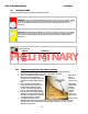
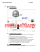
2.10. Radome Assembly Operation
When operating the system it is necessary that the radome access hatch (and/or side door) be closed and secured in
place at all times. This prevents rain, salt water and wind from entering the radome. Water and excessive
condensation promote rust & corrosion of the antenna pedestal. Wind gusts will disturb the antenna pointing.
There are no other operating instructions applicable to the radome assembly by itself.
PRELIMINARY