
Specifications


6009-33 Broadband At Sea Installation
3-4
3.6. Below Decks Equipment.
3.6.1.
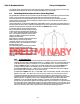
System Configuration
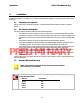
Figure 3-1 Series 09 Simplified Block Diagram
3.6.2.
1. Install the ACU, Terminal Mounting Strip and Multiplexer Panel in your standard 19” Equipment
Rack.
Installing the Below Deck Equipment
2. Connect this equipment as shown in the System Block Diagram.
3. Install and connect your other Below Decks Equipment (ie, Satellite Modem, telephone and
computer equipment).
4. Connect the two coaxes from the Radome Assembly to the BDE Rack.
5. Connect Ships Gyro Compass input to the Terminal Mounting Strip on the rear of the BDE Rack.
6. Connect TMS Transmit mute and positive Satellite ID function lines to Satellite modem.
7. Connect the appropriate power cable into the receptacle of the racks power strip.
8. Plug the power cord into a suitable 110, or 220, VAC UPS or AC power outlet.
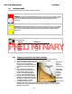
3.6.3.
The DAC-2202 ACU is installed in a BDE Rack and is one rack unit high. It includes a Terminal Mounting Strip
mounted on the rear of the rack which is also a one rack unit high plate.
Antenna Control Unit Connections
PRELIMINARY