
Specifications


6009-33 Broadband At Sea Scheduled Preventive Maintenance
6-4
c. If the damage is at the power ring, replace the power ring (refer to the “replacing the power ring”
procedure in the Maintenance section of this chapter),
2. Inspect the Coaxes at the bracket on the radome base, through the pedestal base and at the dual
channel rotary joint. Inspect both coaxes to assure that they are flexible and that the insulation is
not brittle, chaffed or pinched. If any damage is found repair or replace the damaged coaxes. If
damage is due to chaffing, pinching or crushing reroute the new conductors as necessary to prevent
future damage. Assure that all the connectors are properly tightened.
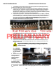
3. Inspect the wire-rope isolators - Wire Rope Isolators should not be frayed, completely compressed,
or otherwise damaged.- The metal bars on the top & bottom of the wire-rope isolators should not be
bent or bowed in any way. If there is any evidence of rust, broken stand(s) of wire or bent bars in
any one of the wire-rope isolators, notify your dealer immediately to obtain replacements and
replace all 4 wire rope isolators immediately (refer to the “replacing the wire-rope isolators”
procedure in the Maintenance section of this chapter).
4. Inspect vertical isolation linear bearing assembly. Look for metal shavings, plastic dust residue or
loose ball bearings on the frame and base plate below the assembly. If any damage is found, notify
your dealer immediately.
5. Inspect all harnesses and connections - The harnesses should not be frayed and all the connectors
should be properly fastened and retainer screws tightened.
6. Inspect all hardware, checking for any loose hardware, loose assemblies (PCU, Power Supply, BUC or
Motor Driver) or counter-weights. .
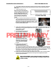
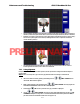
7. Inspect the Azimuth Motor/Encoder, sprockets, drive chain, chain tensioner and spring. If any of
these show signs of rust or corrosion, apply a light coat of “3-in-1” oil using a lit-free cloth on the
affected metal surfaces.
CAUTION: Be EXTREMELY carful rotating the pedestal around while you
fingers are in this area to prevent pinching or crushing your fingers in the
pedestal assembly.
a. Assure that
none of the motor
mounting hardware is
coming loose. Tighten
any loose hardware
found.
b. Check the motor cable
for damage and that the
retaining screws are
tightened to keep the
connector properly
terminated .
c. Visually verify that the
sprockets are properly
aligned so that the chain
travels smoothly through
the motor sprocket, the chain tensioner sprocket and the driven sprocket.
d. Inspect chain - should not be rusted or corroded, apply light coat of oil on the chain using a lint free
cloth.
PRELIMINARY