
Specifications


Scheduled Preventive Maintenance 6009-33 Broadband At Sea
6-5
e. Verify that the ends of the chain tensioner spring are properly hooked in the brackets and that the
spring is not stretched. Rotate the chain tensioner away from chain to verify positive spring tension
against chain.
f. Using a screw driver or hook,
disconnect one end of the spring and
measure its length from inside of hook on
one end to the inside of the hook on the
other end. Replace the spring if it is
stretched or damaged in any way (refer
to the replacing the chain tensioner
spring procedure in the maintenance
chapter.
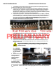
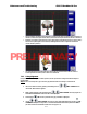
8. Inspect home switch sensor proximity to the metal home
plate. When aligned with the plate, the end of the sensor
should not be more than 0.125 inch (0.318cm) from the metal
plate (refer to home flag sensor alignment procedure . Assure
that the home flag target ring clamp is tight so that it does not
rotate around the pedestal spindle.
9. Inspect vertical isolation linear bearing blocks. Look for metal shavings, plastic dust residue or loose
ball bearings on the frame and base plate below the assembly. If any signs of wear or failure are
noted, contact your dealer
immediately for repair.
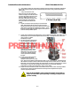
10. The vertical isolation spring should
not be completely compressed or
otherwise damaged. Verify that
the gap between the upper pair of
rubber bumpers and the top of the
striker plate and the gap between
the lower pair of rubber bumpers
and bottom of the striker plate is
approximately the same. If the
striker plate is very near the upper,
or lower, pair of rubber bumpers,
contact your dealer immediately
for repair.
11. Inspect the pneumatic dampener
to assure that the mounting
hardware at each end is not coming
loose. Bounce the pedestal by applying pressure down on the cross-level beam. A whistling sound
will be heard as air expels out from, and is sucked in through, the flow control valves. If a valve has
failed, refer to the “pneumatic dampener valve replacement” procedure in the Maintenance section
of this chapter. If the pneumatic dampener has failed, refer to the “pneumatic dampener
replacement” procedure in the Maintenance section of this chapter
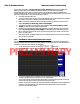
12. Inspect the Cross-Level Motor and belt. Assure that there are no loose motor mounting hardware.
Check the motor cable for damage and that the retaining screws are tightened to keep the
connector properly terminated.
CAUTION: Be EXTREMELY careful rotating the pedestal around while you
fingers are in this area to prevent pinching or crushing your fingers in the
pedestal assembly.
PRELIMINARY