
Specifications


6009-33 Broadband At Sea Maintenance and Troubleshooting
7-2
OFF to balance the antenna. . Do NOT remove any of the drive belts. Balancing is accomplished by
adding or removing balance trim weights at strategic locations to keep the antenna from falling
forward/backward or side to side. The antenna system is not pendulous so 'balanced' is defined as the
antenna remaining at rest when left in any position. The antenna should be balanced within one ounce at the
typical trim weight location of 10 inches from the axis of rotation.
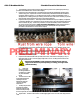
1. Turn Antenna power breaker ON
2. To turn OFF antenna drive (AZ, EL & CL) follow the Pedestal Control Unit Configuration procedure in
this chapter to set the PCU configuration to (N0000) but do NOT save.
3. Balance the antenna elevation axis with the elevation near horizon (referred to as front to back
balance) by adding, or subtracting, small counter-weights.
4. Then balance Cross Level axis (referred to as left-right balance) by moving existing counter-
weights. Do NOT add counter-weight during this step.
5. Last, balance the Elevation Axis with the antenna pointed at zenith (referred to as top to bottom
balance) by moving existing counter-weights. Do NOT add counter-weight during this step.
6. When completed, the antenna will stay at any position it is pointed in for at least 5 minutes (with
little, to no, ship motion).
7. Turn antenna power OFF, and then back ON, to re-Initialize the antenna. This will also turn antenna
drive (AZ, EL & CL) back ON.
7.2.2.
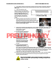
The DacRemP DISPTC graph chart provides a means for monitoring torque commands required for each
motor for diagnostic purposes and verifying antenna balance. By observing each trace, the required drive of
the antenna via the motor driver PCB may be established.
Fine Balance and Monitoring Motor Drive Torque
• To view the Torque Commands, select the graph chart.
• This chart displays the Torque Command errors for each axis via three traces, CL (Cross Level), LV
(Elevation), and AZ (Azimuth), at a fixed 0.195amps/vertical division.
• A normal trace display will be ± 1 divisions from the red reference line while under calm sea
conditions and with DishScan Drive turned off. See example below
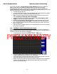
• The Cross Level display will decrease (plots below red line) as the antenna requires drive to the left
and increase (plots above red line) as the antenna requires to the right.
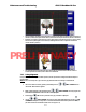
Example: The antenna pictured in the screen capture below is imbalanced so that it is “Right Heavy”.
The CL trace is plotting above the red reference line (indicating that drive CCW is required to
maintain a 90°Cross-Level position).
PRELIMINARY