
Specifications


Maintenance and Troubleshooting 6009-33 Broadband At Sea
7-3
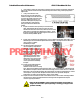
• The Level display should decrease (plots below red line) as the antenna requires drive forward (Up in
elevation) and increase (plots above red line) as the antenna requires drive back (Down in elevation).
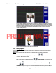
• Example: The antenna pictured in the screen capture below is imbalanced so that it is “Front Heavy”.
The LV trace is plotting above the red line (indicating that drive CW is required to maintain the
current elevation position).
• The Azimuth display should decrease (plots below red line) as the antenna is driven CCW and
increase (plots above red line) as the antenna is rotated CW.
7.2.3.
If the polarization motor or pot have been replaced, use this procedure to realign the feed assembly and
potentiometer.
Polang Alignment
Step 1
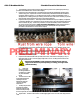
1. Get into the ‘SETUP’ mode by pressing and holding the two
: In the ACU setup menu, go to the Pol Type parameter and set to Polang to manual Mode:
LEFT & RIGHT arrows
until the ‘EL TRIM’ window appears.
2. Briefly release and then push and release both
LEFT & RIGHT arrow keys again. The
‘SAVE NEW PARAMETERS’ window should now be displayed.
3. Push either the
‘UP’ arrow key until the ‘Pol Type’ parameter is displayed.
4. Use the
LEFT & RIGHT arrow keys to select appropriate digits then use the ‘UP
& DOWN’ arrow keys to change value. For Manual Polarization Mode set this parameter to 9. (To
put antenna into Auto Polarization Mode set to Pol Type to 72)
PRELIMINARY