
Specifications


6009-33 Broadband At Sea 6009-33 Technical Specifications
8-6
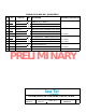
8.10. Cables
8.10.1. Antenna Control Cable (Provided from ACU to the Base MUX)
RS-422 Pedestal Interface
Type Shielded Twisted Pairs
Number of wires 4
Wire Gauge 24 AWG or larger
Communications Parameters: 9600 Baud, 8 bits, No parity
Interface Protocol: RS-422
Interface Connector: DE-9P
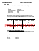
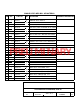
8.10.2. Antenna L-Band IF Coax Cables (Customer Furnished)
Due to the loss across the length of the RF coaxes at L-Band, Sea Tel recommends the following 50 ohm coax
cable types (and their equivalent conductor size) for our standard pedestal installations. Type N male
connectors installed on the cables MUST be 50 Ohm connectors for the center pin to properly mate with
the female adapters we provide on the Base multiplexer panel and on the adapter bracket mounted inside the
radome next to the breaker box.:
Run
Length
Coax
Type
Typical. Loss @
1750Mhz
Shield
isolation
Center
Conductor
Size
Installed
Bend
Radius
Tensile
Strength
<100 ft LMR-240 10.704 db per
100 ft(30.48 m)
>90db 0.056 In.
(1.42 mm)
2.5 In. (63.5
mm)
80lb
(36.3 kg)
up to
150 ft
LMR-400 5.571 db per
100 ft(30.48 m)
>90db 0.108 In.
(2.74 mm)
4.0 in.
(101.6 mm)
160lb
(72.6 kg)
up to
200 ft
LMR-500 4.496 db per
100 ft(30.48 m)
>90db 0.142 In.
(3.61 mm)
5.0 In.
(127 mm)
260lb
(118 kg)
Up to
300 ft
LMR-600 3.615 db per
100 ft(30.48 m)
>90db 0.176 In.
(4.47 mm)
6.0 In.
(152.4 mm)
350lb
(158.9 kg)
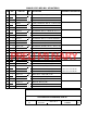
8.10.3. Multi-conductor Cables (Customer Furnished)
Due to the voltage loss across the multi-conductor cables, Sea Tel recommends the following wire gauge for
the AC & DC multi-conductor cables used in our standard pedestal installations:
Run Length Conductor Size
up to 50 ft 20 AWG (0.8 mm)
up to 100 ft 18 AWG (1.0 mm)
up to 150 ft 16 AWG (1.3 mm)
up to 250 ft 14 AWG (1.6 mm)
Up to 350 ft 12 AWG (2.0 mm)
PRELIMINARY