
Technical data


Section 08 ELECTRICAL SYSTEM
Sub-Section 05 (INSTRUMENTS AND ACCESSORIES)
08-05-2
– Adjust potentiometer to the resistance values
as per following chart to test accuracy of
gauge.
NOTE : Gauge must be activated to obtain a
reading.
If gauge is not within the specifications, replace it.
Variable Trim Gauge
The trim gauge shows the riding angle of the wa-
tercraft.
1. Bow up
2. Bow down
Accuracy of gauge can be checked with a potenti-
ometer.
– Disconnect 2-circuit connector housing of
BROWN / BLACK and BROWN / WHITE wires
of gauge.
– Connect potentiometer test probes to BROWN
/ BLACK and BROWN / WHITE wires of gauge.
– Adjust potentiometer to the resistance values
as per following chart to test accuracy of gauge.
NOTE : Gauge must be activated to obtain a
reading.
If gauge is not within the specifications, replace it.
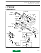
Fuel Baffle Pick-Up Sensor
The baffle pick-up has an integrated fuel sensor
(except SP and HX models).
To verify fuel sensor, a resistance test should be
performed with an ohmmeter allowing the float to
move up through a sequence.
1. Pick-up tube
2. Fuel sensor
3. Baffle pick-up
RESISTANCE
(Ω)
FUEL LEVEL
LCD GRAPHIC
LOW FUEL
LEVEL RED
LIGHT
0 ± 2.2
0
FULL OFF
17.8 ± 2.2 7/8 OFF
27.8 ± 2.2 3/4 OFF
37.8 ± 2.2 5/8 OFF
47.8 ± 2.2 1/2 OFF
57.8 ± 2.2 3/8 OFF
67.8 ± 2.2 1/4 OFF
77.8 ± 2.2 1/8 ON
89.0 ± 2.2 EMPTY ON
VTS
Bombardier
F01H4RA
1
2
RESISTANCE (Ω)
GAUGE NEEDLE
POSITION
10 -45°
95 0°
180 + 45°
VTS
Bombardier
F01H0EA
+ 45°
0°
- 45°
F01F20A
1
2
3
www.SeaDooManuals.net