
Technical data


Section 08 ELECTRICAL SYSTEM
Sub-Section 05 (INSTRUMENTS AND ACCESSORIES)
08-05-4
NOTE : This sensor turns the low-level oil
light to ON if the connector has been forgot-
ten unconnected even when there is enough oil in
tank.
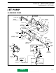
Speed Sensor
The speedometer gives a reading through a
speed sensor. Speed sensor is installed on ride
shoe. It works with the water flow which turns a
magnetic paddle wheel that triggers an electronic
pick-up that in turn sends a speed signal to the
speedometer.
The paddle wheel is protected by the pick-up
housing.
1. Pick-up housing
2. Paddle wheel
STATIC TEST
To verify speed sensor, a resistance test can be
performed with an ohmmeter. Disconnect speed
sensor wires from inside bilge.
Refer to the following chart for speed sensor test-
ing. Always respect polarity in chart.
DYNAMIC TEST
To verify speed sensor, a dynamic test can also be
performed using a battery and a voltmeter.
Disconnect speed sensor wires from inside bilge.
With a 12 VDC battery, connect the positive (+) to
sensor PURPLE / YELLOW wire.
Connect the negative (-) to the sensor BLACK
wire.
Connect the voltmeter positive probe to sensor
BLUE / PURPLE wire and the negative probe to
sensor BLACK wire.
Turn the paddle wheel slowly. There should be a
voltage fluctuation.
VTS Switch
Always confirm first that the fuse is in good con-
dition.
Disconnect BLACK wire, BLUE / WHITE wire and
GREEN / WHITE wire of VTS switch located in
front of bilge on left side.
Using an ohmmeter, connect test probes to
switch BLACK and BLUE / WHITE wires ; then,
connect test probes to switch BLACK and GREEN
/ WHITE wires.
Measure resistance ; in both test, it should be
high when button is released and must be close
to zero when activated.
METER (-)
LEAD
METER (+)
LEAD
APPROX.
VALUE
Purple/Yellow Black ∝
Black Purple/Yellow 21.8 MΩ
Blue/Purple Black 3.6 MΩ
Black Blue/Purple ∝
Purple/Yellow Blue/Purple ∝
Blue/Purple Purple/Yellow 3 MΩ
2
1
F01H3VA
F04H20A
BATTERY
VOLTMETER
BLUE /
PURPLE
BLACK
PURPLE /
YELLOW
www.SeaDooManuals.net