
Technical data


Section 08 ELECTRICAL SYSTEM
Sub-Section 05 (INSTRUMENTS AND ACCESSORIES)
08-05-5
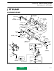
VTS Motor
Always confirm first that the fuse is in good con-
dition.
Motor condition can be checked with an ohmme-
ter. Install test probes on both BLUE / ORANGE
and GREEN / ORANGE wires. Measure resis-
tance, it should be close to 1.5 ohm.
If motor seems to jam and it has not reached the
end of its stroke, the following test could be per-
formed.
First remove motor, refer to PROPULSION SYS-
TEM 09-04. Then manually rotate worm to verify
VTS system actuating mechanism for free opera-
tion.
Connect motor through a 15 A fuse directly to the
battery.
Connect wires one way then reverse polarities to
verify motor rotation in both ways.
If VTS actuating mechanism is correct and the
motor turns freely in both ways, VTS module
could be defective.
VTS Control Module
It receives its current from the battery. It is pro-
tected by its own 7.5 A fuse.
RESISTANCE TEST
Disconnect BROWN / BLACK wire and BROWN /
WHITE wire of VTS control module located in
front of bilge on left side.
Connect test probes of an ohmmeter to BROWN
/BLACK wire and BROWN / WHITE wire of VTS
control module.
NOTE : To permit VTS actuation when en-
gine is not running, remove safety lanyard
from switch and depress start / stop button to ac-
tivate delay timer.
Push on VTS switch down position until motor
stops.
Read the resistance on the ohmmeter, it should
indicate a resistance of 24 ohms ± 1%.
Push on VTS switch up position until motor stops.
Read the resistance on the ohmmeter, it should
indicate a resistance of 167 ohms ± 1%.
For a complete resistance test from UP to DOWN
position, refer to the following chart.
NOTE : If the VTS control module passes
this resistance test, it doesn’t mean it is in
perfect condition.
RESISTANCE (Ω)
NOZZLE
POSITION
167.3 ± 1 % UP
153.0 ± 4 %
138.7 ± 1 %
124.4 ± 1 %
110.1 ± 1 %
95.8 ± 1 %
81.5 ± 1 %
67.2 ± 1 %
52.9 ± 1 %
38.6 ± 1 %
24.3 ± 1 % DOWN
www.SeaDooManuals.net