Product Manual Cheetah 15K.5 SCSI ST3300655LW ST3300655LC ST3146855LW ST3146855LC ST373455LW ST373455LC 100384776 Rev.
©2007, Seagate Technology LLC All rights reserved. Publication number: 100384776, Rev. F November 2007 Seagate, Seagate Technology and the Wave logo are registered trademarks of Seagate Technology LLC in the United States and/or other countries. Cheetah, SeaTools and SeaTDD are either trademarks or registered trademarks of Seagate Technology LLC or one of its affiliated companies in the United States and/ or other countries.
Contents 1.0 Scope . . . . . . . . . . . . . . . . . . . . . . . . . . . . . . . . . . . . . . . . . . . . . . . . . . . . . . . . . . . . . . . . . . . . . . . . 1 2.0 Applicable standards and reference documentation . . . . . . . . . . . . . . . . . . . . . . . . . . . . . . . . . 2.1 Standards . . . . . . . . . . . . . . . . . . . . . . . . . . . . . . . . . . . . . . . . . . . . . . . . . . . . . . . . . . . . . . 2.1.1 Electromagnetic compatibility. . . . . . . . . . . . . . . . . . . . . . . . . .
6.4.1 Temperature . . . . . . . . . . . . . . . . . . . . . . . . . . . . . . . . . . . . . . . . . . . . . . . . . . . . 6.4.2 Relative humidity . . . . . . . . . . . . . . . . . . . . . . . . . . . . . . . . . . . . . . . . . . . . . . . . 6.4.3 Effective altitude (sea level) . . . . . . . . . . . . . . . . . . . . . . . . . . . . . . . . . . . . . . . . 6.4.4 Shock and vibration . . . . . . . . . . . . . . . . . . . . . . . . . . . . . . . . . . . . . . . . . . . . . . 6.4.5 Air cleanliness . . . . . . .
List of Figures Figure 1. Figure 2. Figure 3. Figure 4. Figure 5. Figure 6. Figure 7. Figure 8. Figure 9. Figure 10. Figure 11. Figure 12. Figure 13. Figure 14. Figure 15. Figure 16. Figure 17. Typical ST3300655LW drive +5 V LVD current profile . . . . . . . . . . . . . . . . . . . . . . . . . . . . . . ST3300655LC DC current and power vs. IOPS (LVD) . . . . . . . . . . . . . . . . . . . . . . . . . . . . . . ST3146855LC DC current and power vs. IOPS (LVD) . . . . . . . . . . . . . . . . . . . . . . . . .
1.0 Scope This manual describes Seagate® Technology LLC, Cheetah® 15K.5 SCSI disc drives. Cheetah 15K.5 SCSI drives support the small computer system interface (SCSI) as described in the ANSI SCSI SPI-4 interface specifications to the extent described in this manual. The SCSI Interface Manual (part number 100293069) describes general SCSI interface characteristics of this and other families of Seagate drives. From this point on in this product manual the reference to Cheetah 15K.
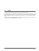
2 Cheetah 15K.5 SCSI Product Manual, Rev.
2.0 Applicable standards and reference documentation The drive has been developed as a system peripheral to the highest standards of design and construction. The drive depends upon its host equipment to provide adequate power and environment in order to achieve optimum performance and compliance with applicable industry and governmental regulations. Special attention must be given in the areas of safety, power distribution, shielding, audible noise control, and temperature regulation.
2.2 Electromagnetic compliance Seagate uses an independent laboratory to confirm compliance to the directives/standard(s) for CE Marking and C-Tick Marking. The drive was tested in a representative system for typical applications. The selected system represents the most popular characteristics for test platforms. The system configurations include: • Typical current use microprocessor • 3.
Seagate also has internal systems in place to ensure ongoing compliance with the RoHS Directive and all laws and regulations which restrict chemical content in electronic products. These systems include standard operating procedures that ensure that restricted substances are not utilized in our manufacturing operations, laboratory analytical validation testing, and an internal auditing process to ensure that all standard operating procedures are complied with. 2.4 Reference documents Cheetah 15K.
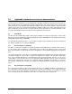
6 Cheetah 15K.5 SCSI Product Manual, Rev.
3.0 General description Cheetah 15K.5 SCSI drives combine Tunneling Magnetoresistive (TMR) heads and a wide Ultra320 SCSI interface to provide high performance, high capacity data storage for a variety of systems including engineering workstations, network servers, mainframes, and supercomputers. Ultra320 SCSI uses negotiated transfer rates.
An automatic shipping lock prevents potential damage to the heads and discs that results from movement during shipping and handling. The shipping lock automatically disengages when power is applied to the drive and the head load process begins. A high-performance actuator assembly with a low-inertia, balanced, patented, straight-arm design provides excellent performance with minimal power dissipation. 3.1 Standard features The Cheetah 15K.
3.3 Performance • Supports industry standard Ultra320 SCSI interface • Programmable multi-segmentable cache buffer (see Section 4.5) • 15k RPM spindle. Average latency = 2.0 msec • Command queuing of up to 64 commands • Background processing of queue • Supports start and stop commands (spindle stops spinning) 3.4 Reliability • Annualized Failure Rate (AFR) of 0.62% • Increased LSI circuitry integration • Incorporates industry-standard Self-Monitoring, Analysis and Reporting Technology (S.M.A.R.T.
3.5.1 Programmable drive capacity Using the Mode Select command, the drive can change its capacity to something less than maximum. See the Mode Select Parameter List table in the SCSI Interface Manual. Refer to the Parameter list block descriptor number of blocks field. A value of zero in the number of blocks field indicates that the drive shall not change the capacity it is currently formatted to have.
4.0 Performance characteristics 4.1 Internal drive characteristics (transparent to user) Drive capacity Read/write heads Tracks/surface (total) Tracks/inch Peak bits/inch Areal Density Internal data rate Disc rotational speed Average rotational latency ST3300655LW ST3300655LC ST3146855LW ST3146855LC ST373455LW ST373455LC 300.0 8 74,340 125,000 890k 110 960 to 1607 15k 2.0 146.8 4 74,340 125,000 890k 110 960 to 1607 15k 2.0 73.4 2 74,340 125,000 890k 110 960 to 1607 15k 2.
4.2.1 Seek time Not including controller overhead (msec)1,2 Read Write Average Typical 3.5 4.0 Single Track Typical 0.2 0.4 Full Stroke Typical 6.8 7.5 1. Typical access times are measured under nominal conditions of temperature, voltage, and horizontal orientation as measured on a representative sample of drives. Access to data = access time + latency time. 2. 4.2.
4.3 Start/stop time After DC power at nominal voltage has been applied, the drive becomes ready within 20 seconds if the Motor Start Option is disabled (i.e., the motor starts as soon as the power has been applied). If a recoverable error condition is detected during the start sequence, the drive executes a recovery procedure which may cause the time to become ready to exceed 20 seconds.
Each cache segment is actually a self-contained circular buffer whose length is an integer number of logical blocks. The drive dynamically creates and removes segments based on the workload. The wrap-around capability of the individual segments greatly enhances the cache’s overall performance. Note. 4.5.1 The size of each segment is not reported by Mode Sense command page 08h, bytes 14 and 15. The value 0XFFFF is always reported regardless of the actual size of the segment.
5.0 Reliability specifications The following reliability specifications assume correct host/drive operational interface, including all interface timings, power supply voltages, environmental requirements and drive mounting constraints (see Section 8.4).
5.1.3 Seek errors A seek error is defined as a failure of the drive to position the heads to the addressed track. After detecting an initial seek error, the drive automatically performs an error recovery process. If the error recovery process fails, a seek positioning error (Error code = 15h or 02h) will be reported with a Hardware error (04h) in the Sense Key. Recoverable seek errors are specified at Less than 10 errors in 108 seeks.
5.2.3 Hot plugging Cheetah 15K.5 SCSI disc drives The ANSI SPI-4 document defines the physical requirements for removal and insertion of SCSI devices on the SCSI bus. Four cases are addressed. The cases are differentiated by the state of the SCSI bus when the removal or insertion occurs.
Controlling S.M.A.R.T. The operating mode of S.M.A.R.T. is controlled by the DEXCPT bit and the PERF bit of the “Informational Exceptions Control Mode Page” (1Ch). The DEXCPT bit is used to enable or disable the S.M.A.R.T. process. Setting the DEXCPT bit will disable all S.M.A.R.T. functions. When enabled, S.M.A.R.T. will collect on-line data as the drive performs normal read/write operations.
zero) whenever the error rate is acceptable. This counter is referred to as the Failure History Counter. There is a separate Failure History Counter for each attribute. Should the counter continually be incremented such that it reaches the predictive threshold, a predictive failure is signaled. 5.2.5 Thermal monitor Cheetah 15K.5 SCSI drives implement a temperature warning system which: 1. Signals the host if the temperature exceeds a value which would threaten the drive. 2.
5.2.6.1 DST Failure Definition The drive will present a “diagnostic failed” condition through the self-tests results value of the diagnostic log page if a functional failure is encountered during DST. The channel and servo parameters are not modified to test the drive more stringently, and the number of retries are not reduced. All retries and recovery processes are enabled during the test.
Short test (Function Code: 001b) The purpose of the short test is to provide a time-limited test that tests as much of the drive as possible within 120 seconds. The short test does not scan the entire media surface, but does some fundamental tests and scans portions of the media. A complete read/verify scan is not performed and only factual failures will report a fault condition. This option provides a quick confidence test of the drive.
Shipping When transporting or shipping a drive, a Seagate approved container must be used. Keep your original box. They are easily identified by the Seagate-approved package label. Shipping a drive in a non-approved container voids the drive warranty. Seagate repair centers may refuse receipt of components improperly packaged or obviously damaged in transit. Contact your Authorized Seagate Distributor to purchase additional boxes.
6.0 Physical/electrical specifications This section provides information relating to the physical and electrical characteristics of the Cheetah 15K.5 SCSI drive. 6.1 AC power requirements None. 6.2 DC power requirements The voltage and current requirements for a single drive are shown in the following table. Values indicated apply at the drive power connector. The tables show current values in Amperes.
Table 4: ST3146855LC DC power requirements LVD mode Notes Voltage Regulation +5 V +12 V [5] ±5% ±5% [2] Average idle current DC X [1][6] 0.71 0.57 Maximum starting current (peak DC) DC (peak AC) AC 3σ 3σ [3] [3] 0.74 1.04 1.94 3.32 Delayed motor start (max) DC 3σ [1] [4] 0.56 0.03 X [1] [1] 0.67 0.68 1.42 0.88 0.94 2.
starting current must be available to each device. 4. Parameters, other than spindle start, are measured after a 10-minute warm up. 5. No terminator power. 6.2.1 Conducted noise immunity Noise is specified as a periodic and random distribution of frequencies covering a band from DC to 10 MHz. Maximum allowed noise values given below are peak-to-peak measurements and apply at the drive power connector. +5 V = +12 V = 6.2.2 250 mV pp from 0 to 100 kHz to 20 MHz. 800 mV pp from 100 Hz to 8 KHz.
Figure 1. Typical ST3300655LW drive +12V LVD current profile Figure 2. Typical ST3300655LW drive +5 V LVD current profile 26 Cheetah 15K.5 SCSI Product Manual, Rev.
6.3 Power dissipation ST3300655LW/ST3300655LC For drives using low voltage differential interface circuits, typical power dissipation under idle conditions is 13.1 watts (44.70 BTUs per hour). To obtain operating power for typical random read operations, refer to the following I/O rate curve (see Figure 3). Locate the typical I/O rate for a drive in your system on the horizontal axis and read the corresponding +5 volt current, +12 volt current, and total watts on the vertical axis.
ST3146855LW/ST3146855LC For drives using low voltage differential interface circuits, typical power dissipation under idle conditions is 10.39 watts (35.45 BTUs per hour). To obtain operating power for typical random read operations, refer to the following I/O rate curve (see Figure 4). Locate the typical I/O rate for a drive in your system on the horizontal axis and read the corresponding +5 volt current, +12 volt current, and total watts on the vertical axis.
ST373455LW/ST373455LC For drives using low voltage differential interface circuits, typical power dissipation under idle conditions is 8.49 watts (28.97 BTUs per hour). To obtain operating power for typical random read operations, refer to the following I/O rate curve (see Figure 5). Locate the typical I/O rate for a drive in your system on the horizontal axis and read the corresponding +5 volt current, +12 volt current, and total watts on the vertical axis. To calculate BTUs per hour, multiply watts by 3.
6.4 Environmental limits Temperature and humidity values experienced by the drive must be such that condensation does not occur on any drive part. Altitude and atmospheric pressure specifications are referenced to a standard day at 58.7°F (14.8°C). Maximum wet bulb temperature is 82°F (28°C). 6.4.1 Temperature a. Operating The maximum allowable continuous or sustained HDA case temperature for the rated Annualized Failure Rate (AFR) is 122°F (50°C). The maximum allowable HDA case temperature is 60°C.
b. Non-operating –1,000 to +40,000 feet (–305 to +12,210 meters) 6.4.4 Shock and vibration Shock and vibration limits specified in this document are measured directly on the drive chassis. If the drive is installed in an enclosure to which the stated shock and/or vibration criteria is applied, resonances may occur internally to the enclosure resulting in drive movement in excess of the stated limits. If this situation is apparent, it may be necessary to modify the enclosure to minimize drive movement.
Drives packaged in single or multipacks with a gross weight of 20 pounds (8.95 kg) or less by Seagate for general freight shipment shall withstand a drop test from 48 inches (1,070 mm) against a concrete floor or equivalent. Z X Y Z Y X Figure 7. 32 Recommended mounting Cheetah 15K.5 SCSI Product Manual, Rev.
6.4.4.2 Vibration a. Operating—normal The drive as installed for normal operation, shall comply with the complete specified performance while subjected to continuous vibration not exceeding 10–500 Hz @ 0.5 G (zero to peak) Vibration may be applied in the X, Y, or Z axis. Operating normal translational random flat profile: 10–500 Hz 0.4 gRMS b.
6.4.7 Acoustics Sound power during idle mode shall be 3.7 bels typical when measured to ISO 7779 specification. Sound power while operating shall be 4.3 bels typical when measured to ISO 7779 specification. There will not be any discrete tones more than 10 dB above the masking noise on typical drives when measured according to Seagate specification 30553-001. There will not be any tones more than 24 dB above the masking noise on any drive. 6.4.8 Electromagnetic susceptibility See Section 2.1.2. 6.
K S REF // T -Z- -Z- [1] L J H B Notes: R REF N -Z- -XA -ZM [1] Mounting holes are 6-32 UNC 2B, three on each side and four on the bottom. Max screw penetration into side of drive is 0.15 in. (3.81 mm). Max screw tightening torque is 6.0 in-lb (3.32 nm) with minimum full thread engagement of 0.12 in. (3.05 mm). C -X- U -XA B C D E F H J K L M N P R S T U P F [1] Dimension Table Millimeters Inches 1.028 max 26.10 max 5.787 max 147.00 max 4.000 ± .010 101.60 ± .25 3.750 ± .010 95.25 ± .25 .125 ± .
36 Cheetah 15K.5 SCSI Product Manual, Rev.
7.0 Defect and error management Seagate continues to use innovative technologies to manage defects and errors. These technologies are designed to increase data integrity, perform drive self-maintenance, and validate proper drive operation. SCSI defect and error management involves drive internal defect/error management and SCSI system error considerations (errors in communications between the initiator and the drive).
Table 6 equates the Read and Write Retry Count with the maximum possible recovery time for read and write recovery of individual LBAs. The times given do not include time taken to perform reallocations, if reallocations are performed. Reallocations are performed when the ARRE bit (for reads) or AWRE bit (for writes) is one, the RC bit is zero, and the Recovery Time Limit for the command has not yet been met. Time needed to perform reallocation is not counted against the Recovery Time Limit.
7.3 SCSI systems errors Information on the reporting of operational errors or faults across the interface is given in the SCSI Interface Product Manual. Message Protocol System is described in the SCSI Interface Product Manual. Several of the messages are used in the SCSI systems error management system. The Request Sense command returns information to the host about numerous kinds of errors or faults. The Receive Diagnostic Results reports the results of diagnostic operations performed by the drive.
7.6 Deferred Auto-Reallocation Deferred Auto-Reallocation (DAR) simplifies reallocation algorithms at the system level by allowing the drive to reallocate unreadable locations on a subsequent write command. Sites are marked for DAR during read operations performed by the drive. When a write command is received for an LBA marked for DAR, the auto-reallocation process is invoked and attempts to rewrite the data to the original location.
8.0 Note. Installation These drives are designed to be used only on single-ended (SE) or low voltage differential (LVD) busses. Do not install these drives on a high voltage differential (HVD) bus. The first thing to do when installing a drive is to set the drive SCSI ID and set up certain operating options. This is usually done by installing small shorting jumpers on the J5 connector (see Figure 10), or via the drive to host I/O signals on the LC model.
Drive HDA (rear view, PCB facing downward) Pin 1 J5 Pin 1 +5V Ground [1] [2] 4P [2] 68 Pin SCSI I/O Connector J1 SCSI ID = 0 3P 2P 1P J1-DC Power (default) PCB SCSI ID = 1 SCSI ID = 2 SCSI ID = 3 SCSI ID = 4 SCSI ID = 5 SCSI ID = 6 For ID selection use jumpers as shown or connect a cable for remote switching as shown below. SCSI ID = 7 SCSI ID = 8 SCSI ID = 9 SCSI ID = 10 SCSI ID = 11 SCSI ID = 12 SCSI ID = 13 SCSI ID = 14 SCSI ID = 15 Reserved Host N.C.
Drive Front Jumper Plug (enlarged to show detail) Pin 1 Reserved J6 [1] [5] T S D MW P P E S E P D Term. Power to SCSI Bus Force Single-ended Bus Mode Delay Motor Start Enable Remote Motor Start Write Protect Parity Disable Figure 11. J6 option select header (on LW models only) 8.1.1 Notes for Figures 10 and 11. [1] Notes explaining the functions of the various jumpers on J5 and J6 jumper header connectors are given here and in Section 8.1.2.
8.1.2 Function description J6 jumper installation SE On Off Forces drive to use single-ended I/O drivers/receivers only. Drive can operate on the interface in low voltage differential mode or single-ended, depending on the voltage state of the I/O “DIFFSNS” line. Default is SE jumper not installed. DS Off Off On ME Off On Off On On WP On Off PD On Off RES Off TP Off On Note. 44 Jumper function description Spindle starts immediately after power up - Default setting.
8.2 Drive orientation The balanced rotary arm actuator design of the drive allows it to be mounted in any orientation. All drive performance characterization, however, has been done with the drive in horizontal (discs level) and vertical (drive on its side) orientations, and these are the two preferred mounting orientations. 8.3 Cooling The host enclosure must provide heat removal from the drive.
8.4 Drive mounting When mounting the drive using the bottom holes (x-y plane in Figure 7) care must be taken to ensure that the drive is not physically distorted due to a stiff non-flat mounting surface . The allowable mounting surface stiffness is 80 lb/in (14.0 N/mm).
9.0 Interface requirements This section partially describes the interface requirements as implemented on the drives. 9.1 General description This section describes in essentially general terms the interface requirements supported by the Cheetah 15K.5 SCSI. No attempt is made to describe all of the minute details of conditions and constraints that must be considered by designers when designing a system in which this family of drives can properly operate.
Table 7: SCSI messages supported by Cheetah 15K.5 SCSI family drives Message name Message code Ordered queue tag 22h Simple queue tag 20h Quick Arbitration and Selection (QAS) 55h Release recovery 10h Restore pointers 03h Save data pointer 02h Synchronous data transfer req. [1] Target transfer disable 13h Terminate I/O process 11h Wide data transfer request [1] Notes. [1] Extended messages (see the SCSI Interface Product Manual). [2] Supports all options except qas_req and iu_req. 9.
Table 8: Commands supported by Cheetah 15K.
Table 8: Commands supported by Cheetah 15K.
Table 8: Commands supported by Cheetah 15K.
Table 9 lists the Standard Inquiry command data that the drive should return to the initiator per the format given in the SCSI Interface Product Manual, part number 100293069, Inquiry command section. Table 9: Cheetah 15K.
9.3.2 Mode Sense data The Mode Sense command provides a means for the drive to report its operating parameters to the initiator. The drive maintains four sets of Mode parameters, Default values, Saved values, Current values and Changeable values. Default values are hard coded in the drive firmware that is stored in flash EPROM nonvolatile memory on the drive PCBA. Default values can be changed only by downloading a complete set of new firmware into the flash EPROM.
Table 10: ST3300655 Mode sense data MODE SENSE HEADER DATA ab 00 10 08 22 ec b2 5c 00 00 02 00 MODE SENSE PAGES DATA SAV 81 0a c0 0b ff 00 00 00 05 00 ff ff DEF 81 0a c0 0b ff 00 00 00 05 00 ff ff CHG 81 0a ff ff 00 00 00 00 ff 00 ff ff SAV 82 0e 80 80 00 0a 00 00 00 00 00 00 00 00 00 00 DEF 82 0e 80 80 00 0a 00 00 00 00 00 00 00 00 00 00 CHG 82 0e ff ff 00 00 00 00 00 00 ff ff 87 00 00 00 SAV 83 16 68 58 00 00 00 38 00 00 03 da 02 00 00 01 00 e6 00 aa 40 00 00 00 DEF 83 16 68 58 00 00 00 38 00 00 03 da 0
Table 11: ST3146855 Mode sense data MODE SENSE HEADER DATA ab 00 10 08 11 17 73 30 00 00 02 00 MODE SENSE PAGES DATA SAV 81 0a c0 0b ff 00 00 00 05 00 ff ff DEF 81 0a c0 0b ff 00 00 00 05 00 ff ff CHG 81 0a ff ff 00 00 00 00 ff 00 ff ff SAV 82 0e 80 80 00 0a 00 00 00 00 00 00 00 00 00 00 DEF 82 0e 80 80 00 0a 00 00 00 00 00 00 00 00 00 00 CHG 82 0e ff ff 00 00 00 00 00 00 ff ff 87 00 00 00 SAV 83 16 34 2c 00 00 00 1c 00 00 03 da 02 00 00 01 00 e6 00 aa 40 00 00 00 DEF 83 16 34 2c 00 00 00 1c 00 00 03 da 0
Table 12: ST373455 Mode sense data MODE SENSE HEADER DATA ab 00 10 08 08 8b b9 98 00 00 02 00 MODE SENSE PAGES DATA SAV 81 0a c0 0b ff 00 00 00 05 00 ff ff DEF 81 0a c0 0b ff 00 00 00 05 00 ff ff CHG 81 0a ff ff 00 00 00 00 ff 00 ff ff SAV 82 0e 80 80 00 0a 00 00 00 00 00 00 00 00 00 00 DEF 82 0e 80 80 00 0a 00 00 00 00 00 00 00 00 00 00 CHG 82 0e ff ff 00 00 00 00 00 00 ff ff 87 00 00 00 SAV 83 16 1a 16 00 00 00 0e 00 00 03 da 02 00 00 01 00 e6 00 aa 40 00 00 00 DEF 83 16 1a 16 00 00 00 0e 00 00 03 da 02
9.4 SCSI bus conditions and miscellaneous features supported Asynchronous SCSI bus conditions supported by the drive are listed below. These conditions cause the SCSI device to perform certain actions and can alter the SCSI bus phase sequence. Other miscellaneous operating features supported are also listed here. Refer to the Parallel SCSI Interface Manual and the SCSI Commands Reference Manual for details.
9.5 Synchronous data transfer The data transfer period to be used by the drive and the initiator is established by an exchange of messages during the Message Phase of operation. See the section on message protocol in the Parallel SCSI Interface Manual and SCSI Commands Reference Manual. 9.5.
9.6.1 DC cable and connector LW model drives receive DC power through a 4-pin connector (see Figure 15 for pin assignment) mounted at the rear of the main PCBA. Recommended part numbers of the mating connector are listed below, but equivalent parts may be used. Type of cable Connector Contacts (20-14 AWG) 14 AWG MP 1-480424-0 AMP 60619-4 (Loose Piece) AMP 61117-4 (Strip) LC model drives receive power through the 80-pin I/O connector. See Tables 19 and 20.
80-pin SCSI I/O Connector Pin 1 J6 Figure 14. LC model drive physical interface (80-pin J1 SCSI I/O connector) 9.6.2 SCSI interface physical description Cheetah 15K.5 SCSI drives support the physical interface requirements of the Ultra320 SCSI Parallel Interface-4 (SPI-4), and operate compatibly at the interface with devices that support earlier SCSI-2 and SCSI-3 standards.
Table 16 shows the interface transfer rates supported by the various drive models defined in this manual. Table 16: Interface transfer rates supported Maximum transfer rate Interface type/ drive models SE LVD Asynchronous Fast-5 Fast-10 Fast-20 (Ultra) Fast-40 (Ultra2) Fast-80 (Ultra160) Fast-160 (Ultra320) ST3300655LW/LC ST3146855LW/LC ST373455LW/LC yes yes yes yes no no no ST3300655LW/LC ST3146855LW/LC ST373455LW/LC yes yes yes yes yes yes yes 9.6.
9.6.4.1 Mating connectors for LW model drives The nonshielded cable connector shall be a 68 conductor connector consisting of two rows of 34 male contacts with adjacent contacts 0.050 inch (1.27 mm) apart. Recommended mating flat cable connector part numbers are: Amp Model 786096-7 Female, 68-pin, panel mount Amp Model 786090-7 Female, 68-pin, cable mount Amp Model 749925-5 (50 mil conductor centers, 28 or 30 AWG wire) Use two, 34 conductor, 50 mil center flat cable with this connector.
Recommended mating 80-position PCBA mount connectors: Straight-in connector Seagate P/N: Amp US P/N: or Amp US P/N: or Amp Japan P/N: Hot plug version (with ground guide-pin) 77678703 2-557103-1 94-0680-02-1 2-557103-2 94-0680-02-2 5-175475-9 787311-1 with polarization 787311-2 without polarization Right-angle to PCBA connectors Seagate P/N: 77678559 Amp US P/N: 2-557101-1 Amp Japan P/N: 5-175474-9 For additional information call Amp FAX service at 1-800-522-6752.
3.650–.005 .346 .155 1.650 .270 .3937 .050 .600 .0787 .022 .200 .020 .047 .60 (15.24) .519 (13.18) .100 (2.54) 1.816 (46.13) .315 (8.00) Position 1 Pos. 1 .20 typ (5.08) 32 4 .218 (5.54) .050 (1.27) Pos. 35 1.650 (41.91) .0787 (2.00) Pos. 68 .980 (24.89) 1.368 (37.74) .840 – .005 (21.34) Pos. 2 .085 x 45¡ chamfer (2.16) typ Pos. 1 .767 (19.48) 1 .315 – .010 (8.00) +.001 .083 —.002dia (2.1) Trifurcated Pins (4 places) 3.650 (92.71) Figure 16.
7.00 (.276) 12.70 (.500) End View Grounding Pins 2.15 +/- 0.10 2 places 57.87 +/- 0.2 (2.278 +/- .008) 0.15 M Y M (.0059) –Y– CL of Datum Y Front View Pin 1 62.15 +/- 0.15 (2.447 +/- 0.006) 0.15 M Y M (.0059) Insert mating I/O connector Housing X Top View Contact 0.50 (.020) 0.3 M Y M (.012) 1.27 (.05) Typ Pin 1 X CL of Datum Y Grounding Pins Pin 40 Back View Pin 41 Figure 17. Pin 80 Nonshielded 80-pin SCSI SCA-2 connector used on LC drives Cheetah 15K.5 SCSI Product Manual, Rev.
Table 17: Note. LW 68-conductor single-ended (SE) P cable signal/pin assignments [11] A minus sign preceding a signal name indicates that signal is active low.
Table 18: Note. LW 68-conductor LVD P cable signal/pin assignments [11] A minus sign preceding a signal name indicates that signal is active low.
Table 19: Note. LC 80-pin single-ended (SE) I/O connector pin assignments [11] A minus sign preceding a signal name indicates that signal is active low.
Table 20: Note. LC 80-pin single-ended (LVD) I/O connector pin assignments [11] A minus sign preceding a signal name indicates that signal is active low.
Notes [ ] for Tables 17 through 20. [1] [2] See Section 9.6.4.1 for detailed electrical characteristics of these signals. The conductor number refers to the conductor position when using 0.025-inch (0.635 mm) centerline flat ribbon cable. Other cables types may be used to implement equivalent contact assignments. [3] Connector contacts are on 0.050 inch (1.27 mm) centers. [4] Front panel LED signal; indicates drive activity for host front panel hard drive activity indicator.
LVD Input characteristics Each differential signal received by LVD interface receiver circuits shall have the following input characteristics when measured at the disc drive connector: Steady state Low level input differential voltage = 0.030 V = < Vin = < 3.6 V (signal negation/logic 0) Steady state High level input differential voltage = –3.6 V = < Vin = < –0.030 V (signal assertion/logic 1) Differential voltage = +0.030 V minimum with common-mode voltage range 0.845 V = < Vcm = < 1.685 V.
Single-ended I/O cable pin assignments for LW drives are shown in Table 18. Single-ended I/O pin assignments for LC models are shown in Table 19. The LC model does not require an I/O cable. It is designed to connect directly to a back panel connector. 9.7.1.3 Cables for low voltage differential drivers/receivers The SPI-3 and SPI-4 specification for differential impedance for LVD cables is 122.5 + 12.5 ohms.
9.8 Terminator requirements Caution: These drives do not have onboard internal terminators. The user, systems integrator or host equipment manufacturer must provide a terminator arrangement external to the drive when termination is required. For LW drives, terminator modules can be purchased that plug between the SCSI I/O cable and the drive I/O connector or on the end of a short I/O cable stub extending past the last cable connector.
9.10 Disc drive SCSI timing Table 24: Disc drive SCSI timing These values are not current Cheetah 15K.5 SCSI values, but are listed for information only. Description Waveform symbol [1] Waveform table [1] Typical timing Target Select Time (no Arbitration) T00 N/A <1 μs Target Select Time (with Arbitration) T01 4.5-1,2 1.93 μs Target Select to Command T02 4.5-1 3.77 μs Target Select to MSG Out T03 4.5-2 1.57 μs Identify MSG to Command T04 4.5-3 3.36 μs Command to Status T05 4.
Table 24: Disc drive SCSI timing (Continued) These values are not current Cheetah 15K.5 SCSI values, but are listed for information only. Waveform symbol [1] Waveform table [1] Typical timing Next CDB Byte Access (Byte 2 of 10) T23.10.2 4.5-4 0.59 μs Next CDB Byte Access (Byte 3 of 10) T23.10.3 4.5-4 0.11 μs ±1 μs Next CDB Byte Access (Byte 4 of 10) T23.10.4 4.5-4 0.12 μs ±1 μs Next CDB Byte Access (Byte 5 of 10) T23.10.5 4.5-4 0.11 μs ±1 μs Next CDB Byte Access (Byte 6 of 10) T23.10.
9.11 Drive activity LED The following table provides drive activity LED status.
10.0 Seagate Technology support services Internet For information regarding Seagate products and services, visit www.seagate.com. Worldwide support is available 24 hours daily by email for your questions. Presales Support: Presales@Seagate.com Technical Support: DiscSupport@Seagate.com Warranty Support: http://www.seagate.com/support/service/index.html mySeagate my.seagate.com is the industry's first Web portal designed specifically for OEMs and distributors.
Customer Service Operations Warranty Service Seagate offers worldwide customer support for Seagate products. Seagate distributors, OEMs and other direct customers should contact their Seagate Customer Service Operations (CSO) representative for warrantyrelated issues. Resellers or end users of drive products should contact their place of purchase or Seagate warranty service for assistance. Have your serial number and model or part number available.
Index Symbols +5 and +12 volt supplies 24 Numerics 68-conductor connector 62 68-pin connector 63 80 conductor connector 62 80 conductor interface 62 80-pin connector option 61 80-pin I/O connector 68, 69 A AC power 23 access time 12 accessories 10 acoustics 34 activity indicator 70 activity LED 76 actuator 45 actuator assembly 8 AFR 15 air cleanliness 33 air flow 45 suggested 45 altitude 30 altitude and atmospheric pressure 30 ambient 30 Annualized Failure Rate 15 Annualized Failure Rates (AFR) 16 ANSI SC
default 43, 44 default mode parameter 41 default value 53 defect/error management 37 defects 37 Deferred Auto-Reallocation 40 delayed motor start option 23, 24, 70 delayed start 44 differential I/O circuit 44 differentiating features 7 dimensions 34 disc rotational speed 11 drive 33 drive activity 70 drive activity LED 76 drive capacity 11 programmable 10 drive default mode parameter 41 drive firmware 53 drive ID 41 drive ID select jumper connector 41 drive ID/option select header 41 drive interface connect
interface timing 15 internal data rate 11 IRAW 40 J J1-auxiliary 41 jumper 10, 41, 43, 44, 70 jumper function description 44 jumper header 43 jumper plug type 41 L landing zone 8 LED 76 logical block address 13 logical characteristics 58 logical segments 13 low voltage differential (LVD) drivers and receivers 8 LVD 70 LVD interface receiver circuits 71 M mating connector 59, 61, 62 mating flat cable connector 62 maximum current requirements 25 maximum operating current 24 maximum starting current 23, 24
power supply voltage 15 power-carrying conductor 62 power-on 41, 70 power-on reset 53 power-up 25, 44 prefetch 13 prefetch (read look-ahead) 13 prefetch mode 13 prefetch operation 13 prefetch segmented cache control 13 preventive maintenance 15, 16 product data page 52 programmable drive capacity 10 R radio interference regulations 3 RCD bit 13 read error rate 15 read error rates 37 read retry count 37 read/write head 11 ready 53 receive diagnostic results 39 receiver circuits 71 recommended mounting 32 Re
TP1 position 44 tracks/inch 11 tracks/surface, total 11 transfer period 58 transmitter receiver circuits 71 Tunneling Magnetoresistive heads 7 U Ultra160 53 Ultra160 mode 48 Ultra160 SCSI interface 7 Ultra320 SCSI controller 8 unformatted 9 Unrecoverable Errors 15 V vibration 31, 33 vital product data 52 volatile memory 53 voltage 23, 24 W warranty 9, 21 wet bulb temperature 30 wide Ultra160 SCSI interface 7 WP jumper 44 write protect 44 write retry count 37 Z zoned bit recording (ZBR) 8 Cheetah 15K.
Seagate Technology LLC 920 Disc Drive, Scotts Valley, California 95066-4544, USA Publication Number: 100384776, Rev.