Acer Extensa 2700 Series Service Guide PRINTED IN TAIWAN
Revision History Please refer to the table below for the updates made on Extensa 2700 service guide.
Copyright Copyright © 2004 by Acer Incorporated. All rights reserved. No part of this publication may be reproduced, transmitted, transcribed, stored in a retrieval system, or translated into any language or computer language, in any form or by any means, electronic, mechanical, magnetic, optical, chemical, manual or otherwise, without the prior written permission of Acer Incorporated. Disclaimer The information in this guide is subject to change without notice.
Conventions The following conventions are used in this manual: IV Screen messages Denotes actual messages that appear on screen. NOTE Gives bits and pieces of additional information related to the current topic. WARNING Alerts you to any damage that might result from doing or not doing specific actions. CAUTION Gives precautionary measures to avoid possible hardware or software problems. IMPORTANT Reminds you to do specific actions relevant to the accomplishment of procedures.
Preface Before using this information and the product it supports, please read the following general information. 1. This Service Guide provides you with all technical information relating to the BASIC CONFIGURATION decided for Acer "global" product offering. To better fit local market requirements and enhance product competitiveness, your regional office MAY have decided to extend the functionality of a machine (e.g. add-on card, modem, or extra memory capability).
Table of Contents Chapter 1 System Introduction 1 Features . . . . . . . . . . . . . . . . . . . . . . . . . . . . . . . . . . . . . . . . . . . . . . . . . . . . . . . . . . . .1 System Block Diagram . . . . . . . . . . . . . . . . . . . . . . . . . . . . . . . . . . . . . . . . . . . . . . . . .3 Board Layout . . . . . . . . . . . . . . . . . . . . . . . . . . . . . . . . . . . . . . . . . . . . . . . . . . . . . . . .4 Top View . . . . . . . . . . . . . . . . . . . . . . . . . . . . . . . . . . . . . .
Table of Contents Removing the RTC Battery . . . . . . . . . . . . . . . . . . . . . . . . . . . . . . . . . . . . . . . . .61 Removing the Fan . . . . . . . . . . . . . . . . . . . . . . . . . . . . . . . . . . . . . . . . . . . . . . . .61 Removing the Thermal Module . . . . . . . . . . . . . . . . . . . . . . . . . . . . . . . . . . . . . .62 Removing the Processor . . . . . . . . . . . . . . . . . . . . . . . . . . . . . . . . . . . . . . . . . . .62 Installing the Processor . . . . . . . . . . . . . .
Appendix C Online Support Information 120 Index VIII
IX
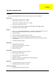
Chapter 1 System Introduction Features This computer was designed with the user in mind. Here are just a few of its many features: Performance T Intel® Pentium® 4 Processor 2.80 ~ 3.06GHz Intel® Pentium® 4 Processor 2.80 ~ 3.20GHz Intel® Pentium® 4 Prescott Processor 3.00 ~ 3.80GHz T Intel® Hyper-ThreadingTM Technology T 256/512MB of DDR333 SDRAM, upgradeable to 2048 MB with dual soDIMM modules T High-capacity, Enhanced-IDE hard disk T The 14.1” or 15” XGA (1024x768 resolution), or 15.
T Stylish appearance T Full-size keyboard with four programmable launch keys T Comfortable palm rest area with well-positioned touchpad T Two Type II or one Type III PC CardBus (PCMCIA) slot T One IEEE 1394 port T One FIR port T One RJ-11 modem jack (V.92, 56K) T One RJ-45 network jack T One DC-in jack T One parallel port (ECP/EPP) T One S-video port T One external monitor port T One microphone-in jack (3.5mm mini jack) T One headphone jack (3.
System Block Diagram Mobile CPU CLK GEN. CY 28346 Portability Mobile P4 3 4, 5 HOST BUS DDR*2 333MHz G768D RGB LVDS GMCH Montara-GT 266/333MHz 9,10 CRT CONN 16 133MHz 12 LCD XGA/SXGA+ 11 6,7,8 HUB I/F Line In Mic In 23 66MHz PCI BUS AC'97 CODEC AC-Link PCI 1520 GHK 25/B/1 CS4299XQ CARDBUS TWO SLOT CARDBUS PWR SW TPS2224A 26 27 27 22 ICH4-M LAN RTL 8101L 21/D/4 Line Out 23 19,20 Mini-PCI OP AMP 802.11A/B/G G1421 21 23 LPC BUS INT.
Board Layout Top View 1 3 2 4 5 67 8 9 10 11 12 13 24 25 4 23 22 21 19 18 20 17 1 CPU Socket 14 Line-in Port 2 Fan Connector 15 Line-out Port 3 SW1 (Please see Chapter 5 for detailed settings) 16 RJ45+RJ11 4 Touchpad Cable Connector Four USB Ports 17 16 14 15 5 HDD Connector 18 VGA Port 6 Keyboard Connector 19 LCD Coaxial Cable Connector 7 Speaker Cable Connector 20 Mini PCI Connector 8 Optical Drive Connector 21 RTC Battery Connector 9 South Bridge 22 North Bri
Bottom View 1 FIR Port 2 Modem Cable Connector 3 Modem Card Connector 4 DIMM Socket 2 5 DIMM Socket 1 Chapter 1 5
Panel Ports allow you to connect peripheral devices to your computer as you would with a desktop PC. Front View # 6 Item Description 1 Display screen Also called LCD (Liquid Crystal Display), displays computer output. 2 Status indicators LEDs (Light Emitting Diodes) that turn on and off to show the status of the computer and its functions and components. 3 Power button Turns the computer on and off. 4 Launch Keys Buttons for launching frequently used programs.
Left view # Icon Item/ Port Description 1 PC Card slots 2 Eject button Eject PC cards from the card slots. 3 Optical drive Internal optical drive; accepts CDs or DVDs depending on the optical drive type. 4 IEEE 1394 port Connects to IEEE 1394 devices. 5 Infrared port Interfaces with infrared devices (e.g., infrared printer, IR-aware computer). 6 LED indicator Lights up when the optical drive is active.
Right View # 8 Item/ Port Description 1 Speaker Delivers stereo audio output. 2 Ventilation slots Enable the computer to stay cool, even after prolonged use. 3 Security keylock Connects to a Kensington-compatible computer security lock.
Rear Panel l # Icon Port Description 1 Power Jack Connects to an AC adapter 2 Parallel port Connects to a parallel device (e.g., parallel printer) 3 Ventilation slots Enable the computer to stay cool, even after prolonged use. 4 S-video port Connects to a television or display device with S-video input. 5 External display port Connects to a display device (e.g., external monitor, LCD projector). 6 Four USB 2.0 ports Connects to any Universal Serial Bus devices(e.g.
Bottom View # 10 Item Description 1 Battery bay Houses the computer’s battery pack. 2 Battery release latch Unlatches the battery to remove the battery pack. 3 Memory compartment Houses the computer’s main memory.
Indicators The computer provides an array of seven indicators located below the display screen, showing the status of the computer and its components. The Power and Sleep status icons are visible even when you close the display cover so you can see the status of the computer while the cover is closed. # Icon Function InviLink Description Indicates status of wireless or Bluetooth (optional) communications. Orange--WLAN; Blue--Bluetooth Chapter 1 1 Power Lights when the computer is on.
Understanding the icons When the cover of your computer is closed, 2 easy-to-read icons are shown, indicating which state or feature is enabled or disabled. # 12 Icon Function Description 1 Power Lights up when the computer is on. 2 Sleep Lights when the computer enters Standby mode and blinks when it enters into or resumes from hibernation mode.
Keyboard The keyboard has full-sized keys and an embedded keypad, separate cursor keys, two Windows keys and twelve function keys. Special keys Lock keys The keyboard has three lock keys which you can toggle on and off. Lock key Caps Lock Description When @is on, all alphabetic characters typed are in uppercase. @ Num Lock (Fn-F11) ] When ] is on, the embedded keypad is in numeric mode. The keys function as a calculator (complete with the arithmetic operators ), -, *, and /).
Embedded numeric keypad The embedded numeric keypad functions like a desktop numeric keypad. It is indicated by small characters located on the upper right corner of the keycaps. To simplify the keyboard legend, cursor-control key symbols are not printed on the keys. Desired access 14 Num lock on Num lock off Number keys on embedded keypad Type numbers using embedded keypad in a normal manner. Cursor-control keys on embedded keypad Hold Shift while using cursor-control keys.
Windows keys The keyboard has two keys that perform Windows-specific functions. Keys Windows logo key Description Start button. Combinations with this key perform shortcut functions. Below are a few examples: + Tab (Activates next taskbar button) + E (Explores My Computer) + F (Finds Document) + M (Minimizes All) j+ + M (Undoes Minimize All) + R (Displays the Run... dialog box) Application key Chapter 1 Opens a context menu (same as a right-click).
Hot Keys The computer employs hot keys or key combinations to access most of the computer’s controls like screen contrast and brightness, volume output and the BIOS Utility. To activate hot keys, press and hold the Fn key before pressing the other key in the hot key combination. Hot Key 16 Icon Function Description Fn-l Hotkey help Displays a list of the hotkeys and their functions. Fn-m Setup Accesses the notebook configuration utility.
Hot Key Icon Function Description Brightness down Decreases the screen brightness. Fn-{ Home Functions as the g key. Fn-} End Functions as the d key. aGr-Euro Euro Types the Euro symbol. Fn-¨z The Euro symbol If your keyboard layout is set to United States-International or United Kingdom or if you have a keyboard with a European layout, you can type the Euro symbol on your keyboard. NOTE: for US keyboard users: The keyboard layout is set when you first set up Windows.
Launch Keys Located at the top of the keyboard are six buttons. These buttons are called lauch keys. They are designated as mail button, Web browser button, P1, P2, Bluetooth and Wireless buttons. The Wireless and Bluetooth buttons cannot be set by the user. To set the other four launch keys, run the Acer Launch Manager.
Hardware Specifications and Configurations System Board Major Chips Item System core logic Controller ® ® Intel Pentium processor+ATI Radeon 9000IGP Super I/O controller NS PC87392 Audio controller Cirrus CS4299-XQ Video controller ATI Radeon 9000IGP Hard disk drive controller Embedded in Intel ICH4 Keyboard controller Mitsubish LPC keyboard controller M38857 CardBus Controller TI 1520 RTC Intel ICH4 Processor Item Specification CPU type Intel® Pentium® processor CPU package To 2.
System Memory Item Specification Memory controller Onboard memory size 0MB DIMM socket number 2 Sockets Supports memory size per socket 128MB Supports maximum memory size 2048MB (Please confirm if 1024MB has passed the test or not) Supports DIMM type DDR-DRAM Supports DIMM Speed 333 MHz Supports DIMM voltage 2.5 V Supports DIMM package 200-pin so-DIMM Memory module combinations You can install memory modules in any combinations as long as they match the above specifications.
LAN Interface Item Chipset Specification RealTek 8101L Supports LAN protocol 10/100Mbps LAN connector type RJ45 LAN connector location Rear side Modem Interface Item Specification Chipset Internal Agere Scorpio chipset (Scorpio+CSP1037B) Fax modem data baud rate (bps) 14.4K Data modem data baud rate (bps) 56K Supports modem protocol V.90/V.92MDC Modem connector type RJ11 Modem connector location Rear side .
CD-ROM Interface Items Specification Vendor & Model Name QSI SCR242 Mitsumi SR244W1 Performance Specification Brust Data Transfer rate PIO mode 4: 16.7 MB/sec Max. (Mode 0~4) Multi-word DMA mode 2: 16.7 MB/sec Max. (Mode 0~2) Ultra DMA mode 2: 33.3MB/sec Max. Access time (typ.
DVD-ROM Interface Item Average Full Access time (typ.) Specification Random DVD-5: CAV mode 110 msec typical 150 msec average max Random 120 msec typical 160 msec average max Full Stroke CAV mode 200 msec typical 260 msec average max Full Stroke 270 msec typical 350 msec average max DVD-9: Random 150 msec typical 200 msec average max Full Stroke 340 msec typical 450 msec average max DVD-RAM (2.
Combo Drive Interface Item Transfer rate (KB/sec) Specification Read Sustained: DVD-ROM MAX 8X CAV (MAX 10800 KB/sec) CD-ROM MAX 24X CAV (MAX 3600 KB/sec) CD-R 4X, 8X (CLV), Max 16X, MAX 24X (ZCLV) Write: CD-RW 4X (CLV) HS-RW 4X,8X, 10X (CLV) ATAPI Interface: PIO mode 16.6 MB/sec :PIO Mode 4 DMA mode 16.6 MB/sec:Multi word mode 2 Ultra DMA mode 33.3MB/sec: Ultra DMA mode 2 Buffer rate 2MB Access time DVD-ROM 180 ms typ.
DVD Dual Interface Item Specification Disc Diameter 12cm and 8cm Capacity 2048 bytes/sector (DVD) 2048 bytes/block (CD Mode-1 and Mode-2 Form-1) 2336 bytes/block (Mode-2) 2328 bytes/block (Mode-2 Form-2) Operation environment for “write/rewrite” application Host Machine IBM compatible PC (Pentium 166 MHz or above) OS MS-Windows 90/ME/2000/XP/NT 4.0 Memory Min.
DVD Dual Interface Item Specification Loading mechanism Manual load/DC brushless mortor system Audio Interface Item Specification Audio Controller Cirrus Logic CS4299-XQ (RTL ALC655 which one is correct? Audio onboard or optional Built-in Mono or Stereo Stereo Resolution 20 bit stereo Digital to Analog converter 18 bit stereo Analog to Digital converter Compatibility Microsoft PC98/PC99, AC97 2.
CRT Display Resolutions 8 bit (256colors) Resolution 16 bits (Hi color) 24 bits (True color) 32 bits (True color) 640x480 Yes Yes Yes Yes 720x480 Yes Yes Yes Yes 800x600 Yes Yes Yes Yes 848x480 Yes Yes Yes Yes 1024x768 Yes Yes Yes Yes 1152x864 Yes Yes Yes Yes 1280x1024 Yes Yes Yes Yes 1400x1050 Yes Yes Yes Yes 1600x1200 Yes Yes Yes Yes Parallel Port Item Specification Parallel port controller NS PC87392 Number of parallel port 1 Location Rear side Co
Keyboard Item Specification Keyboard controller Mitsubishi LPC keyboard controller M38857 Keyboard vendor & model name Darfon/Sunrex Total number of keypads 84-/85- key Windows keys Yes Internal & external keyboard work simultaneously Yes Battery Item Specification Vendor & model name Sanyo/Simplo Battery Type Li-ION Pack capacity 2000mAH per cell Number of battery cell 8 Package configuration 4 serial 2 parallel Output voltage 14.
AC Adapter Item Specification Nominal frequency (Hz) 50-60 Frequency variation range (Hz) 47-63 Input voltage range (Vrms) 90-270 Inrush current The maximum inrush current will be less than 50A and 100A when the adapter is connected to 115Vac and 230Vac respectively. Efficiency It should provide an efficiency of 80% minimum, when measured at maximum load under 115Vac. Output Ratings (CV mode) DC output voltage 19V Noise + Ripple 300mVp-pmax (20 MHz bandwidth) Load 0(min) 3.
Power Management Power Saving Mode Phenomenon Hibernation Mode T All power shuts off T The display shuts off T Hard disk drive is in standby mode. (spindle turned-off) Enter Hibernation Mode (suspend to HDD) when 1.Hibernation hot-key is pressed and system is ready to enter Hibernation mode 2.System Hibernation timer expires and system is ready to enter Hibernation mode. Display Standby Mode Keyboard, built-in touchpad, and an external PS/2 pointing device are idle for a specified period.
Mechanical Specification Item Specification Indicators Power-on, Standby, Battery Status, Media Access, CapsLock and NumLock Switch Power Chapter 1 31
Chapter 2 System Utilities BIOS Setup Utility The BIOS Setup Utility is a hardware configuration program built into your computer’s BIOS (Basic Input/ Output System). Your computer is already properly configured and optimized, and you do not need to run this utility. However, if you encounter configuration problems, you may need to run Setup. Please also refer to Chapter 4 Troubleshooting when problem arises.
Navigating the BIOS Utility There are six menu options: Info., Main, System Devices, Security, Boot, and Exit. Follow these instructions: T To choose a menu, use the cursor left/right keys (zx). T To choose a parameter, use the cursor up/down keys ( wy). T To change the value of a parameter, press por q. T A plus sign (+) indicates the item has sub-items. Press e to expand this item. T Press ^ while you are in any of the menu options to go to the Exit menu.
Information NOTE: The system information is subject to different models. Parameter Floppy Disk Drive Description Shows floppy drive type informaiton. Note: Aspre 1620, Extensa 2700, TravelMate 2500 and Extnesa 2500 series products do not have floppy disk drive; Extensa 2000 and TravelMate 2000 series have floppy disk drive. HDD Model Name This field shows the model name of HDD installed on primary IDE master.
Main The Main screen displays a summary of your computer hardware information, and also includes basic setup parameters. It allows the user to specify standard IBM PC AT system parameters. NOTE: The screen above is for reference only. Actual values may differ.
The table below describes the parameters in this screen. Settings in boldface are the default and suggested parameter settings. Parameter Description Format/Option System Time Sets the system time. The hours are displayed with 24-hour format. Format: HH:MM:SS (hour:minute:second) System Time System Date Sets the system date. Format MM/DD/YYYY (month/day/ year) System Date System Memory This field reports the memory size of the system.
Advanced The Advanced menu screen contains parameters involving your hardware devices. It also provides advanced settings of the system. The table below describes the parameters in the screen. Settings in boldface are the default and suggested parameter settings. Parameter 37 Description Options Hyper-Threading Technology The function is supported only when the CPU installed is 3.06G or above. The system will automatically hide this selection when detecting the CPU frequency is below 3.
Parameter Legacy USB Support Chapter 2 Description Enables, disables USB interface devices support under DOS mode.
Security The Security screen contains parameters that help safeguard and protect your computer from unauthorized use.
The table below describes the parameters in this screen. Settings in boldface are the default and suggested parameter settings. Parameter Description Option User Password is Shows the setting of the user password. Clear or Set Supervisor Password is Shows the setting of the Supervisor password Clear or Set Set User Password Press Enter to set the user password. When set, this password protects the BIOS Setup Utility from unauthorized access.
Removing a Password Follow these steps: 1. Use the w and y keys to highlight the Set Supervisor Password parameter and press the e key. The Set Password box appears: 2. Type the current password in the Enter Current Password field and press e. 3. Press e twice without typing anything in the Enter New Password and Confirm New Password fields. The computer then sets the Supervisor Password parameter to “Clear”. 4.
If the current password entered does not match the actual current password, the screen will show you the Setup Warning. If the new password and confirm new password strings do not match, the screen will display the following message.
Boot This menu allows the user to decide the order of boot devices to load the operating system. Bootable devices includes the distette drive in module bay, the onboard hard disk drive and the CD-ROM in module bay.
Exit The Exit screen contains parameters that help safeguard and protect your computer from unauthorized use. The table below describes the parameters in this screen. Parameter Description Exit Saving Changes Exit System Setup and save your changes to CMOS. Exit Discarding Changes Exit utility without saving setup data to CMOS. Load Setup Default Load default values for all SETUP item. Discard Changes Load previous values from CMOS for all SETUP items. Save Changes Save Setup Data to CMOS.
Diskette before you use the Phlash utility. NOTE: Do not install memory-related drivers (XMS, EMS, DPMI) when you use the Phlash. NOTE: Please use the AC adaptor power supply when you run the Phlash utility. If the battery pack does not contain enough power to finish BIOS flash, you may not boot the system because the BIOS is not completely loaded. Fellow the steps below to run the Phlash. 45 1. Prepare a bootable diskette. 2. Copy the Phlash utilities to the bootable diskette. 3.
Chapter 3 Machine Disassembly and Replacement This chapter contains step-by-step procedures on how to disassemble the notebook computer for maintenance and troubleshooting. To disassemble the computer, you need the following tools: T Wrist grounding strap and conductive mat for preventing electrostatic discharge T Flat-bladed screw driver T Phillips screw driver T Tweezers T Plastic Flat-bladed screw driver Hexed Screw Driver NOTE: The screws for the different components vary in size.
General Information Before You Begin Before proceeding with the disassembly procedure, make sure that you do the following: 47 1. Turn off the power to the system and all peripherals. 2. Unplug the AC adapter and all power and signal cables from the system.
Disassembly Procedure Flowchart The flowchart on the succeeding page gives you a graphic representation on the entire disassembly sequence and instructs you on the components that need to be removed during servicing. For example, if you want to remove the main board, you must first remove the keyboard, then disassemble the inside assembly frame in that order.
LCD Module 4 LCD Cushions E*4 LCD Bezel L*1 Inverter L*4 LCD LCD Panel H*8 for 14.1" H*6 for 15.0" LCD Coaxial Cable LCD Brackets Screw List Item 49 Description A SCW HEX NYL I#R-40/O#4-40 L5.5(34.00015.081) B SCRW MACH PAN NYLOK M2.0*10 NI (86.1A522.100) C SCRW CPU SCREW FORCE 5KGS(86.T30V1.001) D SCREW M2*3 NYLON 1JMCPC420325(86.9A352.3R0) E SCREW M2.5X6(86.9A353.6R0) F SRW M2.5*8L B/ZN NYLOK 700(86.9A353.8R0) G SCREW M3x4(86.9A524.4R0) H SCREW M2X2.0(86.9A552.
Removing the Battery 1. To remove the battery, push the battery release latch. 2. Then slide the battery out from the machine.
Removing the Memory Module 51 1. See “Removing the Battery” on page 50. 2. To remove the memory module from the machine, first remove the two screws holding the dimm cover. 3. Remove the dimm cover. 4. Pop up the memory. 5. Then remove the memory.
Removing the Wireless LAN Board and the Modem Board 1. See “Removing the Battery” on page 50. 2. To remove the wireless LAN board, first remove the two screws holding the modem cover. 3. Remove the modem cover from the machine. 4. Disconnect the wireless antennae. 5. Pop out the wireless LAN board. 6. To remove the modem board, first remove the two screws fastening the modem board. 7. Detach the modem board and disconnect the modem cable carefully, then remove the modem board.
Removing the Hard Disk Drive Module 1. See “Removing the Battery” on page 50. 2. To remove the hard disk drive, pull the hard disk dirve carefully. 3. Then take the hard disk drive out of the main unit. Disassembling the Hard Disk Drive Module 53 1. See “Removing the Battery” on page 50. 2. See “Removing the Hard Disk Drive Module” on page 53. 3. Remove the two screws that fasten the HDD holder. 4. Detach the hard disk drive from the HDD holder.
Removing the LCD Module Removing the Middle Cover 1. See “Removing the Battery” on page 50. 2. To remove the middle cover, first use a plastic flat screwdriver to remove the right hinge cap. 3. Remove the screw that secures the middle cover. 4. Remove the left hinge cap. 5. Then remove the screw holding the middle cover on the other side. 6. Detach the middle cover from the machine. 7. Disconnect the launch board cable then remove the middle cover off the main unit. .
3. Remove the two screws and then detach the launch board from the middle cover. Removing the LCD Module 55 1. See “Removing the Battery” on page 50. 2. See “Removing the Middle Cover” on page 54. 3. See “Removing the Launch Board” on page 54. 4. Remove the screw that fastens the LCD coaxial cable and disconnect the cable. Then disconnect the LCD inverter cable. 5. Remove the four screws holding the LCD hinge; two on the right and two on the left.
Chapter 3 56
Disassembling the LCD Module Removing the LCD Bezel 1. See “Removing the Battery” on page 50. 2. See “Removing the Middle Cover” on page 54. 3. See “Removing the Launch Board” on page 54. 4. See “Removing the LCD Module” on page 55. 5. Use plastic tweezers to remove the four screw pads, and then remove the four screws that fasten the LCD bezel. 6. Snap off the bezel carefully, and then remove the LCD bezel from the LCD module. Removing the Inverter Board (15” LCD) 57 1.
NOTE: Please arrange the LCD inverter cable well to the LCD panel as the picture below shows when you reassemble the LCD module. Removing the 15” TFT LCD 1. See “Removing the Battery” on page 50. 2. See “Removing the Middle Cover” on page 54. 3. See “Removing the Launch Board” on page 54. 4. See “Removing the LCD Module” on page 55. 5. See “Removing the LCD Bezel” on page 57. 6. See “Removing the Inverter Board (15” LCD)” on page 57. 7.
2. See “Removing the Middle Cover” on page 54. 3. See “Removing the Launch Board” on page 54. 4. See “Removing the LCD Module” on page 55. 5. See “Removing the LCD Bezel” on page 57. 6. See “Removing the Inverter Board (15” LCD)” on page 57. 7. See “Removing the 15” TFT LCD” on page 58. 8. Remove the four screws holding the right LCD bracket.Then remove the right bracket. 9. Remove the four screws holding the left LCD bracket. Then remove the left bracket.. Removing the LCD Coaxial Cable 1.
2. See “Removing the Middle Cover” on page 54. 3. See “Removing the Launch Board” on page 54. 4. See “Removing the LCD Module” on page 55. 5. See “Removing the LCD Bezel” on page 57. 6. See “Removing the Inverter Board (15” LCD)” on page 57. 7. See “Removing the 15” TFT LCD” on page 58. 8. Remove the screw holding the right hinge, then remove the right hinge. 9. Remove the screw holding the left hinge, then remove the left hinge.
Disassembling the Main Unit Removing the Keyboard 1. See “Removing the Battery” on page 50. 2. See “Removing the Middle Cover” on page 54. 3. To remove the keyboard, carefully pull the keyboard out and upwards as the pticute shows. 4. Use a plastic tweezers or a plastic flat screwdriver to disconnect the keyboard cable from the main board carefully, then remove the keyboard. Removing the RTC Battery 1. See “Removing the Battery” on page 50. 2. See “Removing the Middle Cover” on page 54. 3.
Removing the Thermal Module 1. See “Removing the Battery” on page 50. 2. See “Removing the Middle Cover” on page 54. 3. See “Removing the Keyboard” on page 61. 4. See “Removing the Fan” on page 61. 5. Disconnect the fan cable then remove the four screws fastening the thermal module. 6. Then remove the thermal module. Removing the Processor 1. See “Removing the Battery” on page 50. 2. See “Removing the Middle Cover” on page 54. 3. See “Removing the Keyboard” on page 61. 4.
Installing the Processor 1. See “Removing the Battery” on page 50. 2. See “Removing the Middle Cover” on page 54. 3. See “Removing the Keyboard” on page 61. 4. See “Removing the RTC Battery” on page 61. 5. See “Removing the Fan” on page 61. 6. See “Removing the Thermal Module” on page 62. 7. Lift up the CPU lever, then place the CPU back to the CPU socket. Please remember to press the CPU lever after you put the CPU back to the socket. Removing the Upper Case Assemly 63 1.
4. Then take the upper case assembly off the main unit. Removing the Touchpad Board 1. See “Removing the Battery” on page 50. 2. See “Removing the Middle Cover” on page 54. 3. See “Removing the Keyboard” on page 61. 4. See “Removing the Upper Case Assemly” on page 63. 5. To detach the touch pad board, first disconnect the touch pad cable from the touch pad board with a plastic tweezers.Then release the touchpad cover lock on the back as the picture shows. 6.
3. See “Removing the LCD Module” on page 55. 4. See “Removing the Keyboard” on page 61. 5. See “Removing the Upper Case Assemly” on page 63. 6. See “Removing the Touchpad Board” on page 64. 7. Remove the touchpad scroll key then remove the touchpad cable. Removing the VGA Thermal Plate 1. See “Removing the Battery” on page 50. 2. See “Removing the Middle Cover” on page 54. 3. See “Removing the Keyboard” on page 61. 4. See “Removing the Fan” on page 61. 5.
Removing the Second Fan Bracket 1. See “Removing the Battery” on page 50. 2. See “Removing the Middle Cover” on page 54. 3. See “Removing the LCD Module” on page 55. 4. See “Removing the RTC Battery” on page 61. 5. See “Removing the Fan” on page 61. 6. See “Removing the Thermal Module” on page 62. 7. Remove the three screws that fasten the second fan bracket then remove the bracket. Removing the ODD Module(1) 1. See “Removing the Battery” on page 50. 2.
Removing the HDD Bracket 1. See “Removing the Battery” on page 50. 2. See “Removing the Middle Cover” on page 54. 3. See “Removing the Keyboard” on page 61. 4. See “Removing the Upper Case Assemly” on page 63. 5. Remove the four screws holding the HDD bracket, then remove the HDD bracket. Removing the Main Board 1. See “Removing the Battery” on page 50. 2. See “Removing the Middle Cover” on page 54. 3. See “Removing the Keyboard” on page 61. 4.
. 13. Remove the two screws holding the main board as the picture shows. Remove another two screws that fasten the main board. Then detach the main board from the lower case carefully. Removing the DC Board 1. See “Removing the Battery” on page 50. 2. See “Removing the Middle Cover” on page 54. 3. See “Removing the Keyboard” on page 61. 4. See “Removing the Upper Case Assemly” on page 63. 5. See “Removing the Fan” on page 61. 6. See “Removing the Thermal Module” on page 62. 7.
3. See “Removing the Keyboard” on page 61. 4. See “Removing the Upper Case Assemly” on page 63. 5. See “Removing the Fan” on page 61. 6. See “Removing the Thermal Module” on page 62. 7. See “Removing the VGA Thermal Plate” on page 65. 8. See “Removing the CPU Heatsink Plate” on page 65. 9. See “Removing the Second Fan Bracket” on page 66. 10. See “Removing the ODD Module(2)” on page 66. 11. See “Removing the HDD Bracket” on page 67. 12. See “Removing the Main Board” on page 67. 13.
Removing the Speaker Set 1. See “Removing the Battery” on page 50. 2. See “Removing the Middle Cover” on page 54. 3. See “Removing the Keyboard” on page 61. 4. See “Removing the Upper Case Assemly” on page 63. 5. See “Removing the Fan” on page 61. 6. See “Removing the Thermal Module” on page 62. 7. See “Removing the VGA Thermal Plate” on page 65. 8. See “Removing the CPU Heatsink Plate” on page 65. 9. See “Removing the Second Fan Bracket” on page 66. 10.
System Upgrade Procedure Base Unit to Wireless Unit 1. Turn out the two screws fastening the modem cover then open the cover. 2. Connect the wirless antennae. 3. Insert the wireless LAN board to the wireless socket on the main board. 4. Close the modem cover and fasten the cover with the two screws. NOTE: You must connect the wireless antennae before you insert the wireless LAN board to the socket.
Chapter 4 Troubleshooting Use the following procedure as a guide for computer problems. NOTE: The diagnostic tests are intended to test only Acer products. Non-Acer products, prototype cards, or modified options can give false errors and invalid system responses. 1. Obtain the failing symptoms in as much detail as possible. 2. Verify the symptoms by attempting to re-create the failure by running the diagnostic test or by repeating the same operation. 3.
System Check Procedures External Diskette Drive Check Do the following to isolate the problem to a controller, driver, or diskette. A write-enabled, diagnostic diskette is required. NOTE: Make sure that the diskette does not have more than one label attached to it. Multiple labels can cause damage to the drive or cause the drive to fail. Do the following to select the test device. 1. Boot from the diagnostics diskette and start the diagnostics program. 2.
Memory check Memory errors might stop system operations, show error messages on the screen, or hang the system. 1. Boot from the diagnostics diskette and start the doagmpstotics program (please refer to main board. 2. Go to the diagnostic memory in the test items. 3. Press F2 in the test items. 4. Follow the instructions in the message window. NOTE: Make sure that the DIMM is fully installed into the connector. A loose connection can cause an error.
Check the Power Adapter Unplug the power adapter cable from the computer and measure the output voltage at the plug of the power adapter cable. See the following figure Pin 1: +19 to +20.5V Pin 2: 0V, Ground 1. If the voltage is not correct, replace the power adapter. 2. If the voltage is within the range, do the following: T Replace the System board. T If the problem is not corrected, see “Undetermined Problems” on page 85. T If the voltage is not correct, go to the next step.
Check the Battery Pack To check the battery pack, do the following: From Software: 1. Check out the Power Management in control Panel 2. In Power Meter, confirm that if the parameters shown in the screen for Current Power Source and Total Battery Power Remaining are correct. 3. Repeat the steps 1 and 2, for both battery and adapter. 4. This helps you identify first the problem is on recharging or discharging. From Hardware: 1. Power off the computer. 2.
Power-On Self-Test (POST) Error Message The POST error message index lists the error message and their possible causes. The most likely cause is listed first. NOTE: Perform the FRU replacement or actions in the sequence shown in FRU/Action column, if the FRU replacement does not solve the problem, put the original part back in the computer. Do not replace a non-defective FRU. This index can also help you determine the next possible FRU to be replaced when servicing a computer.
Index of Error Messages Error Code List Error Codes 006 Error Messages Equipment Configuration Error Causes: 1. CPU BIOS Update Code Mismatch 2. IDE Primary Channel Master Drive Error (THe causes will be shown before “Equipment Configuration Error”) 010 Memory Error at xxxx:xxxx:xxxxh (R:xxxxh, W:xxxxh) 070 Real Time Clock Error 071 CMOS Battery Bad 072 CMOS Checksum Error 110 System disabled. Incorrect password is specified.
Error Message List Error Messages Real time clock error FRU/Action in Sequence RTC battery Run BIOS Setup Utility to reconfigure system time, then reboot system. System board Previous boot incomplete - Default configuration used Run “Load Default Settings” in BIOS Setup Utility. RTC battery System board Memory size found by POST differed from CMOS Run “Load Default Settings” in BIOS Setup Utility.
Error Message List No beep Error Messages No beep, power-on indicator turns off and LCD is blank. FRU/Action in Sequence Power source (battery pack and power adapter). See “Power System Check” on page 74. Ensure every connector is connected tightly and correctly. Reconnect the DIMM. LED board. System board. No beep, power-on indicator turns on and LCD is blank. Power source (battery pack and power adapter). See “Power System Check” on page 74.
Index of Symptom-to-FRU Error Message LCD-Related Symptoms Symptom / Error LCD backlight doesn't work Action in Sequence LCD is too dark Enter BIOS Utility to execute “Load Setup Default Settings”, then reboot system. LCD brightness cannot be adjusted Reconnect the LCD connectors. LCD contrast cannot be adjusted Keyboard (if contrast and brightness function key doesn't work).
PCMCIA-Related Symptoms Symptom / Error System cannot detect the PC Card (PCMCIA) Action in Sequence PCMCIA slot assembly System board PCMCIA slot pin is damaged. PCMCIA slot assembly Memory-Related Symptoms Symptom / Error Memory count (size) appears different from actual size. Action in Sequence Enter BIOS Setup Utility to execute “Load Default Settings, then reboot system. DIMM System board Speaker-Related Symptoms Symptom / Error In Windows, multimedia programs, no sound comes from the computer.
Power Management-Related Symptoms Symptom / Error System hangs intermittently. Action in Sequence Reconnect hard disk/CD-ROM drives. Hard disk connection board System board Peripheral-Related Symptoms Symptom / Error Action in Sequence System configuration does not match the installed devices. Enter BIOS Setup Utility to execute “Load Default Settings”, then reboot system. External display does not work correctly.
Intermittent Problems Intermittent system hang problems can be caused by a variety of reasons that have nothing to do with a hardware defect, such as: cosmic radiation, electrostatic discharge, or software errors. FRU replacement should be considered only when a recurring problem exists. When analyzing an intermittent problem, do the following: 1. Run the advanced diagnostic test for the system board in loop mode at least 10 times. 2. If no error is detected, do not replace any FRU. 3.
Undetermined Problems The diagnostic problems does not identify which adapter or device failed, which installed devices are incorrect, whether a short circuit is suspected, or whether the system is inoperative. Follow these procedures to isolate the failing FRU (do not isolate non-defective FRU). NOTE: Verify that all attached devices are supported by the computer. NOTE: Verify that the power supply being used at the time of the failure is operating correctly. (See “Power System Check” on page 74): 85 1.
How to Build NAPP Master Hard Disc Drive CD to Disk Recovery 1. Prepare NAPP CD, Recovery CD and System CD. 2. Put NAPP CD into the optical drive. Then boot up the system. 3. The system will ask you if you want to build NAPP Master HDD. Please press any key to continue. 4. NAPP CD will start to preload the system, please click [Y]. 5. Select CD to Disk Revocery.
6. Put the Recovery CD to the optical drive. This step is to create image files to the system, you do not have to put the Recovery CD to the optical drive in order. Place one Recovery CD to the drive at one time till you finish all Recovery CDs. After you place the Recovery CD to the optical drive, you will see the display below.
7. Then insert the System CD to the optical drive. 8. You will see the screen displaying “PASS” when the system has buit NAPP Master hard disc drive.
Disk to Disk Recovery 89 1. Prepare NAPP CD, Recovery CD and System CD. 2. Put NAPP CD into the optical drive. Then boot up the system. 3. The system will ask you if you want to build NAPP Master HDD. Please press any key to continue. 4. NAPP CD will start to preload the system, please click [Y].
5. Select Disk to Disk Recovery. Then choose Single Language or Multi-Languages Recovery. NOTE: For Multi-Languages Recovery, not more than five languages could be loaded to the system. 6. Put the Recovery CD to the optical drive. This step is to create image files to the system, you do not have to put the Recovery CD to the optical drive in order. Place one Recovery CD to the drive at one time till you finish all Recovery CDs.
After you place the Recovery CD to the optical drive, you will see the display below. 7. 91 Then insert the System CD to the optical drive.
8. You will see the screen displaying “PASS” when the system has buit NAPP Master hard disc drive.
93 Chapter 4
Chapter 5 Jumper and Connector Locations Top View 1 3 2 4 5 67 8 9 10 11 12 13 24 25 Chapter 5 23 22 21 19 18 20 17 16 14 15 94
95 1 U12 CPU Socket 14 LIN1 Line-in Port 2 FAN1 Fan Connector 15 LOUT1 Line-out Port 3 SW1 SW1 16 RJ1 RJ45+RJ11 4 TPAD1 Touchpad Cable Connector 17 USB1-4 Four USB Ports 5 HDD1 HDD Connector 18 CRT1 VGA Port 6 KB1 Keyboard Connector 19 LCD1 LCD Coaxial Cable Connector 7 SPK1 Speaker Cable Connector 20 MINI1 Mini PCI Connector 8 IDE1 Optical Drive Connector 21 RTC1 RTC Battery Connector 9 U23 South Bridge 22 U15 North Bridge 10 FDD1 FDD Connector 23
Bottom View 1 U7 2 RING1 FIR Port Modem Cable Connector 3 MDC1 Modem Card Connector 4 DM1 DIMM Socket 1 5 DM2 DIMM Socket 2 SW1 Settings 1 2 3 4 Password Enable ON X X X Password Disable OFF X X X Bootblock Enable X ON X X Bootblock Disable X OFF X X Adapter 90W X X ON X Adapter 120W X X OFF X Chapter 5 96
97 Chapter 5
Chapter 6 FRU (Field Replaceable Unit) List This chapter gives you the FRU (Field Replaceable Unit) listing in global configurations of Extensa 2700. Refer to this chapter whenever ordering for parts to repair or for RMA (Return Merchandise Authorization). Please note that WHEN ORDERING FRU PARTS, you should check the most up-to-date information available on your regional web or channel. For whatever reasons a part number change is made, it will not be noted on the printed Service Guide.
Extensa 2700 Exploded Diagram 99 Chapter 6
Picture No. Partname And Description Part Number Adapter ADAPTER 120W 3PIN LITEON PA- AP.T3003.002 1121-02AC REV.A Battery 18 RTC BATTERY 23.T30V1.001 BATTERY MODULE LI-ION 8CELL 2.0 MAH SIMPLO W/ COVER 6M.T30V1.009 BATTERY LI-ION 8CELL 2.0 MAH LI-ION SIMPLO BTP-58A1 BT.T3007.001 BATTERY COVER 42.T30V1.001 DC BOARD 55.T30V1.001 WIRELESS LAN BOARD 802.11B AMBIT T60H656.02 REV.03 54.T30V1.
Picture No. Partname And Description Part Number LAUNCH BOARD 55.T30V1.002 MODEM BOARD 56K AMBIT T60M283.10 54.09011.542 TOUCHPAD CABLE 50.T30V1.001 COVER SWITCH CABLE 50.T30V1.002 LAUNCH CABLE 50.T30V1.011 MODEM CABLE 50.41T11.002 POWER CORD US (3 pin) 27.01618.051 3 MINI PCI CARD PLATE W/RTC HOLDER 60.T30V1.003 6 HINGE CAP RIGHT 42.T30V1.
Picture No. Part Number 8 HINGE CAP LEFT 42.T30V1.003 10 OPTICAL DRIVE SUPPORT BRACKET 33.T30V1.001 15 HDD BRACKET 33.T30V1.002 16 HDD HOLDER 33.T30V1.003 17 LOWER CASE W/ DIMM COVER & MODEM COVER & SPEAKERS 60.T30V1.004 MODEM COVER W/SCREW 42.T30V1.004 DIMM COVER W/SCREW 42.T30V1.005 UPPER CASE W/O COVER SWITCH CABLE & TOUCHPAD MODULE 60.T30V1.
Picture No. Partname And Description Part Number TOUCHPAD COVER 42.T30V1.006 MIDDLE COVE W/LAUNCH BOARD 60.T30V1.005 WIRELESS ANTENNA RIGHT (BLACK) 50.T30V1.004 WIRELESS ANTENNA LEFT (GRAY) 50.T30V1.005 INTEL CELERON PORTABILITY 2.6 GHZ 128K 400FSB for TM240 KC.NCP01.26G INTEL CELERON PORTABILITY 2.5 GHZ 128K 400FSB for TM240 KC.NCP01.25G INTEL CELERON PORTABILITY 2.4 GHZ 128K 400FSB for TM240 KC.NCP01.24G INTEL CELERON PORTABILITY 2.3 GHZ 128K 400FSB for TM240 KC.NCP01.
Picture No. 13 Partname And Description Part Number FDD MODULE 1.44M MCI JU226A033FC 6M.T30V1.003 FDD MODULE 1.44M MITSUMI D353G 4515 6M.T30V1.004 FDD DRIVE 1.44M MCI JU226A033FC KF.T3007.001 FDD DRIVE 1.44M MITSUMI D353G 4515 KF.T3006.001 FDD BRACKET 33.T30V1.005 FDD CABLE 50.T30V1.003 HDD 20GB 2.5" 4200RPM HGST MORAGA IC25N020ATMR04-0 08K0632 KH.02007.002 HDD 20GB/2.5 IN./4200 RPM/IBM CASCADE IC25N020ATCS04-0 07N8325 KH.25202.001 HDD 20GB/2.5 IN./4200RPM/ HITACHI EUCALYPTUS DK23EA KH.
Picture No. Partname And Description Part Number HDD 40GB 2.5" 4200RPM HGST MORAGA IC25N040ATMR04-0 08K0633 KH.04007.004 HDD 40GB/2.5” IN./4200RPM/ TOSHIBA NEPTUNE MK4021GAS KH.34004.001 HDD 40GB 2.5" 5400RPM SEAGATE ST94011A KH.04001.004 HDD 40GB 2.5" 4200RPM FUJITSU V-40 MHT2040AT KH.04006.002 HDD 60GB/2.5 IN./4200RPM/ HITACHI EUCALYPTUS DK23EA60 KH.06005.001 HDD 60GB 2.5" 4200RPM HGST MORAGA IC25N060ATMR04-0 08K0634 KH.06007.002 HDD 60GB/2.5 IN./4200RPM/ TOSHIBA NEPTUNE MK6021GAS KH.
Picture No. 2 Partname And Description Part Number KEYBOARD 84KEY DARFON NSK-AC61D US-INT KB.T3007.001 KEYBOARD 84KEY DARFON NSK-AC602 TAIWAN KB.T3007.002 KEYBOARD 85KEY DARFON NSK-AC60S SPANISH KB.T3007.003 KEYBOARD 84KEY DARFON NSK-AC603 THAI KB.T3007.004 KEYBOARD 85KEY DARFON NSK-AC60U UK KB.T3007.006 KEYBOARD 85KEY DARFON NSK-AC60G GERMAN KB.T3007.007 KEYBOARD 85KEY DARFON NSK-AC606 PORTUGUESE KB.T3007.011 KEYBOARD 84KEY DARFON NSK-AC60C CZECH KB.T3007.015 LCD MODULE 14.
Picture No. NS NS Partname And Description Part Number INVERTER CABLE 50.T30V1.007 LCD COAXIAL CABLE 50.T30V1.008 LCD PANEL W/HINGE & LOGO 60.T30V1.008 LCD BEZEL 14.1" W/ICON LABEL 60.T30V1.006 LCD BEZEL 15" W/ICON LABEL 60.T30V1.007 HINGE PACK 6K.T30V1.001 MAINBOARD W/LAUNCH CABLE & MODEM & MODEM CABLE & PCMCIA SLOT & RTC BATTERY MB.T3001.001 LOGO 31.42S08.001 ICON LABEL 40.T30V1.001 TOUCHPAD SCROLL KEY 42.T30V1.
Picture No. Partname And Description TOUCHPAD KNOB Part Number 42.T30V1.008 LCD SCREW RUBBER UPPER 47.T30V1.001 LCD SCREW RUBBER LOWER 47.T30V1.002 RUBBER FOOT 47.T30V1.003 LCD BEZEL RUBBER UPPER 47.T30V1.004 NAME PLATE TM250 40.T30V1.003 NAME PLATE TM240 40.T30V1.002 MEMORY SO-DIMM DDR266/ 128MB /INFINEON HYS64D16000GDL-7-B KN.12802.004 MEMORY SO-DIMM DDR266/ 128MB/0.14U /NANYA NT128D64SH4B0GM-75B KN.12803.003 MEMORY DDR266 128MB NANYA NT128D64SH4BBGM-75B KN.12803.
Picture No. Partname And Description Part Number MEMORY DDR333 256MB ELPEDIA W30256AAEPI652A KN.25609.002 MEMORY DDR333 256MB MOCRON MT8VDDT3264HDG335C3 KN.25604.009 MEMORY DDR333 512MB INFINEON HYS64D64020GBDL-6B KN.51202.007 CD-ROM MODULE 24X MITSUMI SR244W1 6M.T30V1.001 DVD-ROM MODULE 8X MKE SR8177 6M.T30V1.002 CD-ROM DRIVE 24X W/ BEZEL MITSUMI SR244W1 KD.24X04.002 DVD-ROM DRIVE 8X W/ BEZEL MKE SR-8177 KV.08X02.004 OPTICAL DRIVE BRACKET 33.T30V1.004 PCMCIA SLOT 22.T30V1.
Picture Chapter 6 No. Partname And Description Part Number NS SCREW 86.9A352.3R0 NS SCREW 86.9A353.6R0 NS SCREW 86.9A524.4R0 NS SCREW 86.9A552.2R0 NS SCREW 86.9A552.3R0 NS SCREW 86.9A552.4R0 NS SCREW 86.9A553.3R0 NS SCREW 86.9A553.4R0 NS SCREW 34.00015.
111 Chapter 6
Appendix A Model Definition and Configuration Model Name Definition Model Number 2703LMi Appendix A LCD 15.0" XGA CPU DT P4 3.
113 Appendix A
Appendix B Test Compatible Components This computer’s compatibility is a test plan released by Acer Internal Testing Department. Once the final report is available, this chapter will be revised accordingly.
Microsoft Windows XP Environment Test Item Processor Specifications Northwood 2.60GHz/.13m/512K L2/400Mhz FSB Northwood 2.80GHz/.13m/512K L2/533Mhz FSB/HT Northwood 3.06GHz/.13m/512K L2/533Mhz FSB/HT Northwood 3.0GHz/.13m/512K L2/800Mhz FSB/HT Northwood 3.20GHz/.13m/512K L2/800Mhz FSB/HT Northwood 3.4Ghz/.13m/512K/800FSB/HT Precott 3 GHz/1MB L2/800 FSB/HT Precott 3.2GHz/1MB L2/800 FSB/HT Precott 3.4GHz/1MB L2/800 FSB/HT Precott 3.6GHz/1MB L2/800 FSB/HT Precott 3.8GHz/1MB L2/800 FSB/HT Mobile Pentium 4 3.
Item DVD-dual Specifications DVD-Dual SDW-042 DVD-Dual SDW-431S DVD-Dual GWA-4040N DVD-Dual DVR K13RA DVD-RW DVD-RW SD-R6112 DVD-Super Multi UJ820 DVD super multi AC Adapter (3 pin) Liteon Adapter 135W ADT 135W 3P 19V 0317A19135 HiPro Adapter 135W Power Cord Battery Li-Ion, 8 cells King Cord SANYO BTP-60A1 SIMPLO BTY PK Panasonic Network Adapters LAN Ethernet/10baseT/100baseT 3Com Etherlink III 3C589D IBM EtherJet CardBus Adapter 10/100 Intel Ether Express Pro/100 Mobile Adapter MBLA3200 Xircom C
Item I/O - USB Keyboard/Mouse Specifications Chicony USB Keyboard KU-8933 Microsoft Natural Keyboard Pro Acer Aspire USB mouse Logicool US Mouse Logitech Cordless Mouseman Wheel USB Interface Logitech USB Wheel Mouse M-BB48 Microsoft IntelliMouse Optical USB Interface I/O - Legacy (PS2/Serial) Keyboard/ Mouse IBM 101 key keyboard IBM 109 key keyboard Acer PS2 keyboard Acer KB-101A IBM Numeric Keypad III IBM Numeric Keypad Acer Mouse IBM PS2 Mini Mouse IBM PS2 Mouse Logitech Cordless MouseMan Wheel PS2 in
Item Specifications PCMCIA PCMCIA - ATA IBM Microdrive 340MB IBM Microdrive 1G Iomega Click! 40MB Sony Memory Stick 64MB Sandisk Flash Card 20MB Apacer SD Flash Card 128MB Apacer SD Flash Card 256MB Transcend SD Card 32MB Transcend SD Card 256MB Hagiwara sys-com SD Card 256MBT PCMCIA - USB 2.0 Apricorn EZ-USB2.0 Cardbus PC Card DTK USB 2.
119 Extensa 2700
Appendix C Online Support Information This section describes online technical support services available to help you repair your Acer Systems. If you are a distributor, dealer, ASP or TPM, please refer your technical queries to your local Acer branch office. Acer Branch Offices and Regional Business Units may access our website. However some information sources will require a user i.d. and password. These can be obtained directly from Acer CSD Taiwan.
Index A E AC Adapter 28 Environmental Requirements 30 AFLASH Utility 44 Error Symptom-to-Spare Part Index 77 Audio 19 External CD-ROM Drive Check 73 B F Battery 28 Flash Utility 44 BIOS 19 FRU (Field Replaceable Unit) List 98 package 19 ROM size 19 ROM type 19 vendor 19 Version 19 H Hard disk 19, 21 Hard Disk Drive Module Disassembly 53 BIOS Supports protocol 19 Hard Disk Standby Mode 30 BIOS Utility 32 Hardware Specifications and Configurations 19 Basic System Settings 37 Navigating 33 On
O Video controller 19 Online Support Information 120 P Panel 5, 96 Bottom 10 Parallel Port 27 PC Card 27 PCMCIA 27 Power Management 29 Power System Check 74 Battery Pack 76 Power Adapter 75 R RTC 19 S Second Level Cache 19 speakers hotkey 16 Standby Mode 29 Super I/O 19 System Check Procedures 73 System Diagnostic Diskette 45 System Memory 20 System Utilities 32 System Utility Diskette 45 T Temperature 30 Test Compatible Components 114 Touchpad 19 touchpad hotkey 16 Touchpad Check 76 Troubleshooting 72