CPUville Z80 Computer Disk and Memory Expansion Instruction Manual By Donn Stewart © 2014 by Donn Stewart 1
Table of Contents Introduction................................................................................................................................................3 Building Tips..............................................................................................................................................5 Building the Disk and Memory Expansion Board.....................................................................................5 Testing and Using the Disk and Memory Expansion.
Introduction The CPUville Disk and Memory Expansion Board is designed to provide the CPUville Z80 computer with 64K RAM memory and an IDE disk interface, allowing the computer to run a disk operating system, such as CP/M1. If CP/M is installed, this gives you access to hundreds of programs in the public domain that will run on the Z80 computer. You need the CPUville serial interface board in order to operate the computer with the disk and memory expansion attached.
software OUT instructions to port 0 or port 1, respectively. This system is necessary because the Z80 computer executes code starting at 0x0000 when taken out of reset, so we need ROM there when the computer starts. But, CP/M needs RAM in locations starting at 0x0000. Hence the need for the two configurations. The expansion board comes with a 2K EPROM with ROM code version 8 and above.
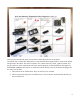
Building Tips See the “Building Tips” section in the CPUville Z80 Computer Kit Instruction Manual for general help. The 40-pin IDE drive connector in this kit has pins that are a little more massive than the IC or component pins. This means that more time will be required to heat these pins with the soldering iron, to ensure good electrical connections. Building the Disk and Memory Expansion Board Start by putting the parts on the organizer to make sure you have them all, and to get familiar with them.
Once you have checked the parts you can start to solder them onto the circuit board. The easiest way to solder the components is to start with the shortest (parts that lie closest to the board) and proceed to the tallest. The order is resistors, ICs, resistor network, sockets, capacitor, LEDs, and 40-pin connector. Some components need to be oriented properly, as described below.
The ICs can be soldered directly to the board without fear of damage if you use a 15-watt or smaller soldering iron. 3. The resistor network can be soldered next. Please note that the marked pin goes to the RIGHT, exactly as shown here: 4. The four 16-pin, two 28-pin, and the one 24-pin sockets are next. They do not need to be oriented. 5. The LEDs are next.
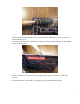
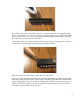
6. The capacitor is next. It does not have to be oriented. 7. Before you solder the 40-pin disk drive connector, take a moment to think about how you will supply power to your disk drive, and if the cable or drive plug you will use is “keyed”. The IDE specification allows for pin 20 to act as a key for orienting the plug in the connector. Here is an example of a keyed plug: If you are using a keyed plug, then you should remove pin 20 from the connector before you solder it in.
If you have a drive with a non-keyed connector, or one that can use the +5V supplied through pin 20, you should leave it in. If you remove pin 20 without cutting it, you can put the pin back in the connector later if you want to, by pushing it back through the plastic with the pliers and screwdriver, like you did when you removed it.
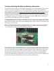
Testing and Using the Disk and Memory Expansion The following sections assume you are familiar with using the CPUville Z80 computer with the serial interface, connected to a terminal, or PC with a terminal emulation program, such as Minicom in Linux, or RealTerm in Windows. If you are not familiar with using the serial interface you should look at the detailed descriptions in the CPUville Z80 Computer Serial Interface Instruction Manual.
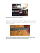
Do the same with the serial interface board, on the right-side connectors. Do not connect a disk to the board at this time. The main computer should have the fast clock selected, and be in Reset. Now, connect power to the computer board. The Power indicators on the disk and memory expansion and serial interface boards should light up. If they don't, check the ribbon cable connectors again to ensure they are seated properly.
You see the same set of commands used in the monitor program version 7, with some new additions. They are diskrd, diskwr, and cpm. The diskrd command This command reads one sector from the disk and writes it into memory at a location you specify. The command takes as input the memory address where the disk data is to be placed as a 4-digit hexadecimal number, and the sector number as a decimal logical block address (LBA) from 0 to 65,535.
If the memory test fails, recheck the pins of the RAM ICs to make sure they are seated properly. If you cannot get it to work, please contact me for advice. If the memory test works, we can be confident that the board is built correctly. Now, put the computer in reset, and disconnect the power, and connect a disk drive as described in the following section.
make it as simple as possible. I did not have any need to use disk space efficiently – I was using a 1 Gb solid-state drive when I developed the system. The disk drive plug needs to be oriented correctly. If keyed, as described above, it cannot go into the connector backwards. However, if it is not keyed, you need to take care that pin 1 of the plug goes onto pin 1 of the connector, which is marked by a 1 with a line on the circuit board, and by a small arrow engraved on the plastic shroud of the connector.
If you are using a compact flash drive in an IDE adapter, you may be able to get power from pin 20 of the drive connector, instead of using separate wires. See the section above in Building the Disk and Memory Expansion for details. Testing the Disk Drive You can test the disk drive using the monitor load, diskwr, diskrd, and dump commands. Of course, once you write to the disk any information on the sector you write to will be overwritten and lost.
sector if you want to use this command to start the operating system. I suggest you do not try to preserve partitions on your disk, but rather dedicate the disk for use on the Z80 computer for experimentation and to try the CP/M operating system. With the disk drive connected, apply power to the computer and take it out of reset. You should again see the greeting message and get the monitor prompt.
You can use whatever pattern you like, but it should be easily recognizable. Now, write the memory page at 0x0800 to disk sector 0 using the diskwr command. You should see a brief flash on the Drive Activity LED when you do this.
If you see your data pattern there, you know your disk is working properly, and you can read and write sectors. You can experiment with other patterns, other memory locations and other sectors. Once the disk is working properly you can install CP/M onto the disk. Installing CP/M version 2.2 About CP/M The CP/M operating system was the first commercially successful disk operating system for microcomputers.
Permission to use CP/M for hobbyist and educational purposes has generally been granted freely, but since I am a commercial enterprise I cannot give you a complete, assembled CP/M system to download. However, there is a web archive of CP/M software, “The Unofficial CP/M Web Site”, that has been granted a license by Lineo, Inc., to make available CP/M source code for download for educational purposes. The site can be found at http://www.cpm.z80.
CHKSUM1: ADD INC DEC JP RET A,(HL) ;and compute sum ignoring carries. HL C NZ,CHKSUM1 ; Those are the only code changes that must be made. However, as mentioned in the Serial Interface Instruction Manual, in the section “A Word about Assemblers”, each assembler program has some quirks that may affect the success of your assembly. The TASM assembler, for example, wants all directives to begin with a period (“.”). Thus, you need .EQU instead of EQU, and .ORG instead of ORG.
CMMND1: LD CALL CALL ADD CALL LD CALL CALL SP,CCPSTACK ;set stack straight. CRLF ;start a new line on the screen. GETDSK ;get current drive. A,'a' PRINT ;print current drive. A,'>' PRINT ;and add prompt. GETINP ;get line from user. ; Change the character in the ADD A,'a' instruction to an upper case A: ; CMMND1: LD CALL CALL ADD CALL LD CALL CALL SP,CCPSTACK ;set stack straight. CRLF ;start a new line on the screen. GETDSK ;get current drive. A,'A' PRINT ;print current drive.
This is important to remember, because in order to prepare the disk, we will need to use the CBIOS calls for writing 0xE5 to the disks. That way, we will write the sectors as CP/M will see them when it creates the file system directory entries. The format program calls to the CBIOS to write 0xE5 to all the sectors of the four CP/M disks in our system. In order to work properly, the CBIOS code needs to placed into the system memory at location 0xFA00 before we load and execute the format program.
The Drive Activity LED should light up for about a minute and a half while the format program fills the CP/M disk with 0xE5. When the light goes off, the monitor prompt should re-appear. The disk is now ready for the CP/M files to be placed on it.2 Putting the CP/M System Files onto the disk The CP/M file system set up in the CBIOS reserves the first 2 tracks of each disk for the system files.
Then, use bload to place the putsys.bin file into memory at location 0x0800: Now, run the putsys program at 0x0800. The drive activity light will light briefly – we are writing many fewer sectors than we wrote with the format program. Now, CP/M will be present on the disk system tracks. Installing the CP/M loader The final piece of the puzzle is to place the cpm_loader program into sector 0 of the hard disk.
We will use the bload command to first place the file cpm_loader.bin into the computer memory, then use the diskwr command to put it into sector 0 on the hard disk: Now that the disk is set up to run CP/M, enter the cpm command at the monitor prompt (you might need to reset the computer to get it to work properly): You now see the CP/M prompt, A>, which indicates that CP/M is running, and that disk A is active. To summarize, these are the steps to install CP/M 2.2: 1. Load z80_cbios.bin at 0xFA00 2.
7. Run putsys.bin 8. Load cpm_loader.bin at 0x0800 9. Write the memory page 0x0800 to disk sector 0 10. Reset the computer 11. Start CP/M using the monitor cpm command. Running CP/M Built-in commands I will not attempt to reproduce here a guide to running CP/M. The original Digital Research CP/M 2 system manual has been converted into a web page: http://www.gaby.de/cpm/manuals/archive/cpm22htm/. Here one can find all the details about using the system, with all the commands listed.
We can rename the file with the REN command: Note that the target file name comes first in the argument for the REN command. Each disk maintains a separate directory for each of multiple users, from 0 to 15. This feature is not of much use to us, but for completeness we can demonstrate it.
You can see user 1 has no files on disk A. Now create a file, with the name test2.com. Switch back to user 0, and display the directory. You see only test1.com. Switch to user 1, and do DIR, and you see that user's test2.com file. User 1's files are not visible to user 0, and vice-versa. We can erase files with the ERA command.
enter the disk letter followed by a colon: If you try to access a disk that is not available, you will get an error message. Hit return and the system will go back to the A disk: This is a very limited set of commands. Many more commands are available as transient commands. Transient commands Originally, CP/M was created with multiple floppy disks, and the first disk came from the manufacturer with lots of programs (transient commands, or .
binary file into memory at 0x0100 , switch to CP/M, and use the built in SAVE command to create a .COM file. So how to get the RAM monitor program itself into memory, and onto the CP/M disk? We “bootstrap” it, using the RAM monitor program itself. It is a little complicated, but you only have to do this once. Here is how. First, we start CP/M with the monitor cpm command. This puts the CP/M system into the memory, and sets up memory page 0 (addresses 0x0000 to 0x00FF) with the data CP/M needs to operate.
Now we can safely load the RAM monitor into memory at 0xDBF2: 31
Then, we run some tiny code (again entered with the load command) to switch to memory configuration 1 and run the RAM monitor: 0800 D3 01 out (1),A ;switch to memory configuration 1 (allRAM) 0802 C3 00 DC jp 0DC00h ;jump to start of RAM monitor Now you see a monitor prompt (>), but it is from the RAM monitor, and not the ROM monitor. To verify this, look at the first page of memory with the dump command: There you see the CP/M warm start jump command at location 0x0000 with some other data.
Now switch to CP/M by entering the monitor cpm command. When CP/M starts (it does a warm boot here), it copies its code from the disk to the memory locations from 0xE400 and higher, but leaves the rest of the memory undisturbed. So, the image of the RAM monitor at 0x0100 is safe. Now, we can use the SAVE command to create the file MONITOR.COM. We have to tell CP/M how many memory pages to save (one page = 256 bytes). If we divide the size of the monitor.bin file by 256 we get 2008/256 = 7.84.
Check the disk directory, and you will see the MONITOR.COM file in place. Once this file is on the disk, all we need to do is enter MONITOR at the CP/M prompt, and we can use the monitor commands to do binary file transfers.
commands can be obtained from The Unofficial CP/M Web Site. The binaries from a CP/M distribution disk are here: http://www.cpm.z80.de/download/cpm22-b.zip. The important ones are PIP.COM, ED.COM, ASM.COM, LOAD.COM, and STAT.COM. There is also DUMP.COM which displays file contents. Let's use the MONITOR and SAVE commands to get STAT.COM onto our computer. Download a copy of STAT.
If you execute the STAT command, you can see how much room is available on the active CP/M disk: If you give STAT a file name argument, it will tell you how big the file is: 36
This concludes a description of the basics of using CP/M, including how to get binary files into the CP/M file system through the serial port of the Z80 computer. The Digital Research CP/M 2 System Manual, available on-line as stated above, explains how to use CP/M in full detail. There are thousands of CP/M programs available, both on the web sites mentioned above, and on other archives. The Humongous CP/M Software Archives at http://www.classiccmp.org/cpmarchives/ is just one example.
Disk and Memory Expansion Schematics and Explanations IDE Interface The IDE interface portion of the disk and memory is simpler than you might suppose.
signals, with +5V and ground power lines, are brought to the disk and memory board through the P1 and P2 connectors. The data and control lines are passed to the serial interface through the P4 connector. Note the bit of logic with inputs from A1 to A3, with the outputs Add 2 or 3, and Add 0 or 1. This logic was needed because the serial interface board has minimal chip select logic on it, and will be activated for any input/output request for port addresses with A1 = 1.
Memory Configuration Logic This logic circuit creates the chip select signals for the ROM and RAM chips, depending on the configuration (see the Memory ICs and Configuration Flip-flop schematic) and the address requested. It is implemented with two-input logic gates and inverters on the 9 ICs that take up most of the room on the circuit board.
• Assert CS_ROM if Configuration is 0, Mem_Req is asserted, and the address is 0x0000 to 0x07FF – that is, if A11 to A15 are all zero. • Assert CS_RAM0 if Configuration is 0, Mem_Req is asserted, and the address is 0x0800 to 0x7FFF – that is, A15 is zero, and any of A11 to A15 is 1.
Memory ICs and Configuration Flip-flop The upper part of the schematic shows a logic circuit that creates a clock pulse that is fed to the configuration flip-flop when an OUT (0),A or OUT (1),A instruction is executed.
logic seen in the previous schematic. The outputs of the chip select logic will select one of the three memory ICs, either the ROM, or one of the two 32K static RAMs for memory access. The logic is designed so that only one of these three ICs is active at any time. Note that the system Reset* signal is fed to the flip-flop. This ensures that the flip-flop is in configuration 0 when the system starts, which is necessary for code execution to start in the ROM.
Disk and Memory Expansion Parts Organizer and List Capacitor, 0.01 uF ceramic Red LED 1 DIL28 socket, 0.3 inch DIL 24 socket 2 74LS08 2 2 74LS32 40-pin IDE connector 74LS00 1 74LS74 2716 EPROM 0.
Selected Program Listings ROM monitor3 # File 2K_ROM_8.asm 0000 ;ROM monitor for a system with serial interface and IDE disk and memory expansion board. 0000 ;Expansion board has 64K RAM -- computer board memory decoder disabled (J2 off).
0005 0007 0009 000b 000c 000c 000c 000c 000d 000f 0011 0014 0015 0017 0018 0018 0018 0018 0018 001a 001c 001f 0020 0021 0022 0024 0025 0028 0028 0028 0028 002a 002c 002f 0031 0032 0033 0034 0035 0036 d3 03 3e 37 d3 03 c9 47 db e6 ca 78 d3 c9 03 01 0d 00 02 db e6 ca 7e a7 c8 d3 23 c3 03 01 18 00 db e6 ca db 77 23 0b 78 b1 c2 03 02 28 00 02 02 18 00 28 00 out ld out ret (3),a a,037h (3),a ;write to control port ;enable receive and transmit ;write to control port ; ;Puts a single char (byte value)
0039 003a 003a 003a 003a 003c 003e 0041 0042 0044 0045 0046 0047 0048 004b 004c 004c 004c 004c 004c 004c 004c 004c 004e 004f 0050 0051 0052 0054 0056 0059 005b 005d 005e 0060 0063 0065 0068 006b 006c c9 db e6 ca 7e d3 23 0b 78 b1 c2 c9 03 01 3a 00 0e 7c 57 7d 5f db e6 ca db fe c8 fe ca fe ca cd 12 13 00 02 3a 00 03 02 52 00 02 0d 7f 74 00 08 74 00 0c 00 ret ; ;Binary dump to port.
006d 006e 0070 0071 0074 0075 0077 007a 007b 007c 007e 007f 0082 0085 0088 0088 0088 0088 0088 0088 0089 008b 008d 008f 0091 0093 0094 0095 0098 0099 009a 009b 009c 009d 009e 00a0 00a1 00a2 00a5 00a6 0c 3e 12 c3 79 fe ca 1b 0d 3e 12 21 cd c3 47 cb cb cb cb 16 5f e5 21 19 7e e1 77 23 78 e6 5f e5 21 19 7e 00 52 00 00 52 00 00 84 03 18 00 52 00 3f 3f 3f 3f 00 ee 00 0f ee 00 get_line_backspace: inc ld ld jp ld cp jp dec dec ld ld ld call jp c a,000h (de),a get_line_next_char a,c 000h z,get_line_next_cha
00a7 00a8 00a9 00aa 00ac 00ad 00ae 00ae 00ae 00ae 00ae 00ae 00ae 00b1 00b3 00b5 00b6 00b9 00ba 00bd 00be 00bf 00c2 00c3 00c4 00c6 00c7 00c7 00c7 00c7 00c7 00c7 00c7 00c8 00c9 00cc 00cd 00cf 00d2 00d4 e1 77 23 3e 00 77 c9 21 06 0e be ca 05 fa 0c 23 c3 79 c9 3e c9 7e e5 cd e1 fe ca cb cb ee 00 0f 00 c2 00 c4 00 b5 00 ff ae 00 ff ec 00 27 27 pop ld inc ld ld ret hl (hl),a hl a,000h (hl),a ;get string target address ;store second char of string ;point to third location ;zero to terminate string ;store t
00d6 00d8 00da 00db 00dc 00dd 00de 00e1 00e2 00e4 00e7 00e8 00e9 00ea 00eb 00ec 00ed 00ee 00fe 00fe 00fe 00fe 00fe 0101 0104 0107 010a 010d 0110 0113 0116 0119 011c 011f 0120 0123 0126 0129 0129 0129 cb cb 57 23 7e e5 cd e1 fe ca b2 23 37 3f c9 37 c9 ..
0129 012c 012f 0132 0135 0136 0139 013c 013f 013f 013f 013f 013f 013f 0140 0141 0144 0147 014a 014d 0150 0151 0154 0155 0156 0158 015b 015e 0161 0162 0163 0164 0165 0167 016a 016c 016f 0172 0173 0174 21 cd 21 cd d0 21 cd c3 42 4b 22 21 22 21 22 0b 2a 37 3f ed da ca 2a 37 3f c9 0a d6 fa fe f2 2a 5e 23 56 08 4c 08 3f db 00 db 01 36 04 18 00 29 01 00 00 06 8f 04 db 00 db 01 db 00 db 42 64 01 64 01 06 db 30 8a 01 0a 8a 01 04 db decimal_entry: ld call ld call ret ld call jp hl,buffer get_line ;return
0175 0176 0179 017c 017d 0180 0181 0184 0187 018a 018b 018c 018f 0199 0199 0199 0199 0199 019c 019e 01a1 01a4 01a7 01aa 01ab 01ac 01af 01b2 01b5 01b8 01bb 01be 01bf 01c2 01c5 01c8 01ca 01cd 01ce 01d1 23 22 2a 3d fa 19 c3 22 c3 37 c9 c3 01 inc hl ;hl now points to next value ld (value_pointer),hl ld hl,(current_value) ;get back current value decimal_add: dec a ;add loop to increase total value 84 01 jp m,decimal_add_done ;end of multiplication add hl,de 7c 01 jp decimal_add 06 db decimal_add_done: ld (curr
01d3 01d6 01d9 01db 01de 01e1 01e4 01e5 01e8 01eb 01ee 01f1 01f4 01f5 01f8 01fb 01fe 0201 0203 0206 0209 020b 020e 020f 0212 0213 0213 0213 0213 0213 0213 0216 0219 021c 021f 0222 0224 0227 022a 022d cd c3 3e 32 cd 2a 7c 21 cd 21 cd 2a 7d 21 cd 21 cd 3e cd c3 3e 21 77 cd c9 22 21 cd c3 cd fe ca 32 cd fe 0c a7 00 02 89 00 00 01 08 88 08 18 00 db 00 db 00 db 08 88 08 18 20 0c a7 00 08 db 00 db 00 db 02 db 00 01 db 89 02 00 ee 18 66 7f 0d 7b 08 7f 0d dump_new_line: db 03 00 02 02 02 db 02 dump_d
022f 0232 0235 0238 023b 023e 0241 0242 0243 0246 0249 024c 024f 0252 0255 0257 025a 025b 025e 0260 0263 0266 0268 026b 026e 0271 0274 0277 027a 027b 027e 027f 027f 027f 027f 0281 0283 0286 0288 0289 ca 32 21 cd da 2a 77 23 22 3a cd 3a cd 3a fe ca 3c 32 3e cd c3 3e 32 cd c3 cd 21 cd c9 cd c9 7b 09 08 c7 71 00 02 db db 00 02 db 00 08 0c 09 0c 02 0f 66 db db 00 db 00 db 02 20 0c 1f 00 02 89 1f 89 1b 18 db db e6 ca db c9 03 02 7f 02 02 02 00 02 db 02 02 02 04 00 89 02 jp z,load_done ld (buffer+1),
0289 0289 028b 028e 0290 0293 0294 0294 0294 0294 0294 0294 0294 0296 0298 029b 029d 029f 02a2 02a4 02a6 02a7 02a9 02aa 02ac 02ad 02af 02b1 02b3 02b5 02b7 02b9 02bb 02be 02c0 02c2 02c5 02c7 02c9 02ca 3e cd 3e cd c9 0d 0c 00 0a 0c 00 db e6 c2 db e6 ca 3e d3 79 d3 78 d3 7b d3 3e d3 3e d3 db e6 ca db e6 c2 db db 77 23 0f 80 94 02 0f 40 9b 02 01 0a 0b 0c 0d e0 0e 20 0f 0f 08 b7 02 0f 80 be 02 0f 08 ;Subroutine to start a new line write_newline: ld a,00dh ;ASCII carriage return character call write_char ld
02cb 02cd 02cf 02d2 02d3 02d3 02d3 02d3 02d3 02d3 02d3 02d5 02d7 02da 02dc 02de 02e1 02e3 02e5 02e6 02e8 02e9 02eb 02ec 02ee 02f0 02f2 02f4 02f6 02f8 02fa 02fd 02fe 0300 0301 0303 0305 0308 030a 030c db 0f e6 08 c2 c7 02 c9 db e6 c2 db e6 ca 3e d3 79 d3 78 d3 7b d3 3e d3 3e d3 db e6 ca 7e d3 23 db e6 c2 db e6 c2 0f 80 d3 02 0f 40 da 02 01 0a 0b 0c 0d e0 0e 30 0f 0f 08 f6 02 08 0f 08 fd 02 0f 80 08 03 in and jp ret a,(0fh) 08h nz,read_loop ;check status ;DRQ bit ;loop until cleared ; ;Subroutine to wr
030f 0311 0312 0312 0312 033b 0362 0384 0389 03c2 03ee 041b 0436 0463 0463 0463 0466 0469 046c 046f 0472 0474 0477 047a 047d 0480 0483 0484 0484 0484 0484 0487 0488 0489 048a 048b 048c 048d 048f 0492 db 0f c9 in ret .. .. .. 08 .. .. .. .. .. 00 00 00 1b ..
0495 be 0496 c2 0499 f6 049b ca 049e 13 string 049f 1a 04a0 23 04a1 c3 04a4 03 04a5 03 04a6 03 04a7 c3 04aa 03 04ab 0a 04ac 6f 04ad 03 04ae 0a 04af 67 04b0 c9 04b1 04b1 04b1 04b1 04b1 04b1 04b1 21 04b4 cd 04b7 21 04ba cd 04bd cd 04c0 cd 04c3 cd 04c6 c3 04c9 04c9 04c9 21 04cc cd 04cf 21 04d2 cd match_loop: a4 04 00 aa 04 95 04 no_match: 87 04 parser_exit: 06 18 89 18 fe 89 99 6f 06 00 03 00 00 02 01 04 2d 18 89 18 06 00 03 00 cp jp or jp inc (hl) nz,no_match 000h z,parser_exit de ;compare buffer cha
04d5 04d8 04db 04de 04e1 04e1 04e1 04e4 04e7 04ea 04ed 04f0 04f1 04f1 04f1 04f4 04f7 04fa 04fb 04fc 04fd 04fe 04ff 0500 0502 0505 0506 0508 050b 050c 050f 0510 0511 0512 0515 0518 0518 0518 051b 051e cd cd cd c3 fe 89 13 6f 00 02 02 04 21 cd 21 cd cd e9 5c 18 89 18 fe 06 00 03 00 00 21 cd 01 0a 6f 03 0a 67 7e f6 ca c5 3e cd c1 cd 03 03 03 c3 c3 ee 05 18 00 ba 07 00 15 05 20 0c 00 18 00 fa 04 6f 04 21 91 06 cd 18 00 21 89 03 call call call jp address_entry write_newline memory_load monitor_warm_
0521 0524 0527 052a 052b 052e 0531 0534 0535 0536 0539 053c 053d 0540 0543 0543 0543 0546 0549 054c 054f 0552 0555 0556 0559 055c 055f 0560 0561 0564 0567 056a 056b 056e 0571 0571 0574 0577 057a 057d cd cd cd e5 21 cd cd 44 4d 21 cd e1 cd c3 18 00 fe 00 89 02 21 cd 21 cd cd cd e5 21 cd cd 44 4d 21 cd cd e1 cd c3 d8 18 89 18 fe 89 21 cd 21 cd cd 2f 18 89 18 fe 12 03 18 00 29 01 b4 06 18 00 28 00 6f 04 06 00 03 00 00 02 3b 03 18 00 29 01 08 07 18 00 7f 02 3a 00 6f 04 07 00 03 00 00 call call call pus
0580 0583 0584 0587 058a 058d 058e 058f 0591 0592 0595 0598 059b 059e 05a1 05a4 05a7 05aa 05ab 05ae 05b1 05b4 05b5 05b6 05b8 05b9 05bc 05bf 05c2 05c5 05c7 05ca 05cd 05cd 05d0 05d3 05d6 05d9 05dc 05dc cd e5 21 cd cd 44 4d 1e e1 cd c3 21 cd 21 cd cd cd e5 21 cd cd 44 4d 1e e1 cd c3 21 01 1e cd c3 89 02 d3 6f 00 00 00 94 00 02 04 08 00 21 cd 21 cd c3 eb 18 08 18 6f 05 00 db 00 04 62 03 18 00 29 01 00 94 6f 57 18 89 18 fe 89 02 04 07 00 03 00 00 02 62 03 18 00 29 01 00 02 08 call push ld call call l
05dc 05dc .. 00 05eb .. 00 05ee .. 00 0606 .. 00 062d .. 00 065c .. 00 0691 .. 00 06b4 .. 00 06d8 .. 00 0708 .. 00 072f .. 00 0757 .. 00 0780 0780 .. 00 0785 .. 00 078a .. 00 078f .. 00 0793 .. 00 0795 .. 00 079a .. 00 07a0 .. 00 07a6 .. 00 07ad .. 00 07b4 .. 00 07b8 00 00 07ba 07ba 80 07 b1 07c2 8a 07 e1 07ca 93 07 f1 07d2 9a 07 18 07da a6 07 71 07e2 b4 07 bf 07e6 b8 07 cd 07ea # End of file 07ea 04 04 04 05 05 05 05 ; monitor_message: defm "\r\nROM ver.
Customized BIOS # File z80_cbios.asm 0000 ; skeletal cbios for first level of CP/M 2.0 alteration 0000 ; Modified for CPUville Z80 computer with IDE disk interface 0000 ; Aug, 2014 by Donn Stewart 0000 ; 0000 ccp: equ 0E400h ;base of ccp 0000 bdos: equ 0EC06h ;bdos entry 0000 bios: equ 0FA00h ;base of bios 0000 cdisk: equ 0004h ;address of current disk number 0=a,...
fa33 fa33 fa33 fa33 fa33 fa37 fa3b fa3f fa43 fa43 fa47 fa4b fa4f fa53 fa53 fa57 fa5b fa5f fa63 fa63 fa67 fa6b fa6f fa73 fa73 fa73 fa77 fa7b fa7f fa83 fa87 fa8b fa8d fa8d fa8d fa8f fa90 fa91 fa92 fa94 00 00 36 32 00 00 fc fd 00 00 8d b6 00 00 fa fc 00 00 36 42 00 00 fc fd 00 00 8d d5 00 00 fa fc 00 00 36 52 00 00 fc fd 00 00 8d f4 00 00 fa fc 00 00 36 62 00 00 fc fd 00 00 8d 13 00 00 fa fd 01 19 17 15 14 12 10 07 05 03 02 1a 18 16 0d 0b 09 08 06 04 13 11 0f 0e 0c 0a 1a 00 03 07 00 f2 00
fa96 fa97 fa98 fa9a fa9c fa9c fa9c fa9c fa9c fa9c fa9d faa0 faa3 faa6 faa6 faa6 faa9 faab faae fab1 fab1 fab3 fab5 fab7 fab7 fab7 faba faba fabb fabc fabd fabe fac1 fac2 fac3 fac6 fac6 fac6 fac9 facb c0 00 00 00 02 00 af 32 03 00 32 04 00 c3 ef fa 31 0e cd cd 80 00 00 4d fb 47 fb 06 2c 0e 00 16 02 21 00 e4 c5 d5 e5 4a cd 6b fb c1 c5 cd 77 fb cd 7d fb fe 00 c2 a6 fa defm defm defw defw 192 0 0 2 ;alloc ;alloc ;check ;track 0 1 size offset ; ; end of fixed tables ; ; individual subroutines to perform
face face face facf fad2 fad3 fad4 fad5 fad6 fad9 fad9 fad9 fada fadb fadd fae0 fae0 fae0 fae2 fae3 fae3 fae3 fae4 fae5 fae6 fae9 faea faeb faec faef faef faef faef faf1 faf4 faf7 fafa fafa fafd fb00 e1 11 80 00 19 d1 c1 05 ca ef fa ; ; ; ; no error, move to next sector pop HL ;recall dma address LD DE, 128 ;dma=dma+128 ADD HL,DE ;new dma address is in h, l pop DE ;recall sector address pop BC ;recall number of sectors remaining, and current trk DEC b ;sectors=sectors-1 JP Z,gocpm ;transfer to cp/m if a
fb03 fb03 fb06 fb09 fb09 fb0a fb0d fb0f fb12 fb14 fb15 fb18 fb18 fb18 fb18 fb18 fb18 fb18 fb18 fb1a fb1c fb1f fb21 fb22 fb24 fb25 fb25 fb25 fb27 fb29 fb2c fb2e fb30 fb31 fb31 fb31 fb33 fb35 fb38 fb39 ; 01 80 00 cd 77 fb fb 3a fe da 3e 4f c3 ; 04 00 04 14 fb 00 00 e4 db e6 ca 3e c9 3e c9 03 02 22 fb ff db e6 ca db e6 c9 03 02 25 fb 02 7f db e6 ca 79 d3 03 01 31 fb 00 02 diskok: LD call BC, 80h setdma ei LD cp jp ld LD JP A,(cdisk) disks c,diskok a,0 c, a ccp ;default dma address is 80h ;enabl
fb3b fb3c fb3c fb3c fb3d fb3e fb3e fb3e fb3f fb40 fb40 fb40 fb41 fb42 fb42 fb42 fb42 fb44 fb46 fb47 fb47 fb47 fb47 fb47 fb47 fb47 fb47 fb47 fb49 fb4c fb4d fb4d fb4d fb50 fb51 fb54 fb56 fb57 fb57 fb57 c9 79 c9 af c9 79 c9 3e 1a e6 7f c9 0e 00 cd 66 fb c9 21 00 00 79 32 35 fc fe 04 d0 ret ; list: ;list character from register c LD a, c ;character to register a ret ;null subroutine ; listst: ;return list status (0 if not ready, 1 if ready) XOR a ;0 is always ok to return ret ; punch: ;punch character from
fb57 fb5a fb5b fb5d fb5e fb5f fb60 fb61 fb64 fb65 fb66 fb66 fb66 fb67 fb6a fb6b fb6b fb6b fb6c fb6f fb70 fb70 fb70 fb70 fb70 fb70 fb71 fb72 fb73 fb74 fb76 fb77 fb77 fb77 fb78 fb79 fb7c fb7d fb7d fb7d 3a 35 fc 6f 26 00 29 29 29 29 11 33 fa 19 c9 79 32 2f fc c9 ; settrk: ; setsec: 79 32 31 fc c9 eb 09 c9 6e 26 00 c9 69 60 22 33 fc c9 LD LD LD ADD ADD ADD ADD LD ADD ret A,(diskno) l, a h, 0 HL,HL HL,HL HL,HL HL,HL DE, dpbase HL,DE ;l=disk number 0, 1, 2, 3 ;high order zero ;*2 ;*4 ;*8 ;*16 (size of each
fb7d during the fb7d fb7d fb7d fb7d fb7d fb7d 21 72 fb80 db 0f fb82 e6 80 fb84 c2 80 fb87 db 0f fb89 e6 40 fb8b ca 87 fb8e 3e 01 fb90 d3 0a fb92 3a 31 fb95 d3 0b fb97 3a 2f fb9a d3 0c fb9c 3a 35 fb9f d3 0d fba1 3e e0 fba3 d3 0e fba5 3e 20 fba7 d3 0f fba9 db 0f fbab e6 08 fbad ca a9 fbb0 db 0f fbb2 e6 80 fbb4 c2 b0 fbb7 db 0f fbb9 db 08 fbbb 77 fbbc 23 fbbd db 0f fbbf e6 08 fbc1 c2 b9 fbc4 2a 33 ;Return a 00h in register a if the operation completes properly, and 0lh if an error occurs read.
disk fbc7 11 72 fbca 06 80 fbcc 1a fbcd 77 fbce 23 fbcf 13 fbd0 10 fa fbd2 db 0f fbd4 e6 01 fbd6 c9 fbd7 fbd7 fbd7 fbd7 during the fbd7 fbd7 fbd7 fbd7 fbd7 2a 33 fbda 11 72 fbdd 06 80 fbdf 7e fbe0 12 fbe1 23 fbe2 13 fbe3 10 fa fbe5 21 72 fbe8 db 0f fbea e6 80 fbec c2 e8 fbef db 0f fbf1 e6 40 fbf3 ca ef fbf6 3e 01 fbf8 d3 0a fbfa 3a 31 fbfd d3 0b fbff 3a 2f fd rd_sector_loop: ld ld ld ld inc inc djnz in and ret de,hstbuf b,128 a,(de) (hl),a hl de rd_sector_loop a,(0fh) 01h ;host buffer ;size of CP/M sect
fc02 fc04 fc07 fc09 fc0b fc0d fc0f fc11 fc13 fc15 fc18 fc19 fc1b fc1c fc1e fc20 fc23 fc25 fc27 fc2a fc2c fc2e fc2f fc2f fc2f fc2f fc2f fc2f fc2f fc31 fc33 fc35 fc36 fc36 fc36 fc36 fcb6 fcd5 fcf4 fd13 d3 3a d3 3e d3 3e d3 db e6 ca 7e d3 23 db e6 c2 db e6 c2 db e6 c9 0c 35 fc 0d e0 0e 30 0f 0f 08 11 fc 08 0f 08 18 fc 0f 80 23 fc 0f 01 00... 00... 00... 00... 00... 00... 00... 00... 00...
fd32 00... chk00: fd42 00... chk01: fd52 00... chk02: fd62 00... chk03: fd72 ; fd72 enddat: fd72 datsiz: fd72 00... hstbuf: ds fe72 end # End of file z80_cbios.asm fe72 defs defs defs defs 16 16 16 16 ;check ;check ;check ;check vector vector vector vector 0 1 2 3 equ equ 256 $ ;end of data area $-begdat; ;size of data area ;buffer for host disk sector Format # File format.
0823 3a 65 08 sector_loop: 0826 4f 0827 cd 21 fa 082a ed 4b 67 08 082e cd 24 fa 0831 cd 2a fa 0834 3a 65 08 0837 fe 1a 0839 ca 43 08 083c 3c 083d 32 65 08 0840 c3 23 08 0843 3a 66 08 next_track: 0846 fe 4d 0848 ca 52 08 084b 3c 084c 32 66 08 084f c3 11 08 0852 3a 64 08 next_disk: 0855 3c 0856 fe 04 0858 ca 61 08 085b 32 64 08 085e c3 08 08 0861 c3 6f 04 done: 0864 00 disk: 0865 00 sector: 0866 00 track: 0867 00 00 address: 0869 directory_sector: 0869 0xe5... ds 08e9 00...
Putsys # File putsys.
083f 083f 0841 0844 0847 084a 084b 084e 0850 0853 0856 0857 085a 085e 0861 0864 0867 0869 086c 086d 0870 0873 0876 0877 087a 087d 0880 0881 0883 0e cd 2a 11 19 22 3e 32 3a 4f cd ed cd cd 3a fe ca 3c 32 2a 11 19 22 c3 c3 00 00 01 1e fa 81 08 80 00 81 08 01 80 08 80 08 21 4b 24 2a 80 19 7d fa 81 08 fa fa 08 08 80 08 81 08 80 00 81 08 53 08 6f 04 00 ;Write track 1, sectors 1 to 25 wr_trk_1: ld c,1 call settrk ld hl,(address) ld de,128 add hl,de ld (address),hl ld a,1 ld (sector),a wr_trk_1_loop: ld a,(sec
0000 0000 0000 0000 0000 0800 0800 0802 0805 0808 080b 080d 0810 0813 0816 0818 081b 081c 081f 0822 0825 0826 0829 082c 082c 082e 0831 0834 0837 0838 083b 083d 0840 0843 0846 0848 084b 084c 084f 0852 3e 32 21 22 3e 32 cd 3a fe ca 3c 32 2a 11 19 22 c3 02 84 00 86 00 85 61 84 1a 2c 3e 32 2a 11 19 22 3e 32 cd 3a fe ca 3c 32 2a 11 01 85 08 86 08 80 00 08 e4 08 08 08 08 08 84 08 86 08 80 00 86 08 10 08 86 01 84 61 84 19 5c 08 08 08 08 08 84 08 86 08 80 00 ;This program is loaded into LBA sector 0 of di
0855 0856 0859 085c 085e 0861 0861 0861 0861 0861 0861 0861 0861 0864 0867 0868 086b 086c 086e 0871 0871 0874 0877 0879 087a 087b 087c 087d 087f 0881 0883 0884 0885 0886 0888 19 22 c3 d3 c3 86 08 40 08 01 00 fa 21 3a 4f 3a 47 1e cd 00 09 84 08 2a 11 06 1a 77 23 13 10 db e6 c9 00 00 00 86 08 00 09 80 85 08 00 94 02 fa 0f 01 00 done: add ld jp out jp hl,de (dmaad),hl rd_trk_1_loop (1),a cpm ;switch memory config to all-RAM read: ;Read one CP/M sector from disk 0 ;Track number in 'track' ;Sector
# End of file cpm_loader.
Table of Tested Disk Drives Drive Year of manufacture Size Passed diskrd/diskwr test CP/M installed successfully Mechanical Hard Disk Drives Seagate ST3290A 261.3 Mb Yes Yes, but gave bad sector errors Western Digital Caviar 32500 1996 2559.8 Mb No Not attempted Seagate Medalist 4321 1999 4.3 Gb No Not attempted Seagate Medalist 4310 1999 4.3 Gb No Not attempted Western Digital WD200 2001 20.0 Gb No Not attempted Western Digital WD400 2003 40.
preserve disk contents) Fujitsu MPE3102AT 1999 10.