
Instruction manual

If you have a drive with a non-keyed connector, or one that can use the +5V supplied through
pin 20, you should leave it in. If you remove pin 20 without cutting it, you can put the pin back
in the connector later if you want to, by pushing it back through the plastic with the pliers and
screwdriver, like you did when you removed it.
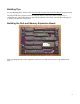
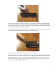
The 40-pin connector is oriented with pin 1 in the left front corner, as shown by the “1” mark on
the circuit board, and the small arrow etched into the plastic shroud:
The cut-out in the shroud should be toward the front of the board.
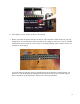
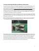
Once you have finished soldering all the pins on the disk and memory expansion board, inspect
the board to make sure there are no solder bridges or unsoldered pins. Hold the finished board
against a bright light. If you can see light coming through a pin hole, you know you forgot to
solder it. This does not apply to the vias, the plated holes where a trace goes from one side of
the board to the other. These can be left open.
9