• • • • • • • • • • • • • • • • • • • • • • • • • • Barracuda 4LP • • • • • • • • • • • • • • • • • • • • • • • • • • • • • • • • • • • • • • • • • • • • • • • • • • • • • • • • • • • • • • • • • • • Disc Drive • • • • • • • • • ST34371N/W/WC/WD/DC • • • • • • • • • • • • • • • • • • • • ST32171N/W/WC/WD/DC • • • • • • • • • • • • • • • • • • • • ST34571N/W/WC/WD/DC • • • • • • • • • • • • • • •
Contents Preface ........................................................................................ 1 Electrostatic discharge protection ................................................ 1 Important safety information and precautions.............................. 2 Wichtige Sicherheitshinweise ...................................................... 4 European Union Compliance ....................................................... 7 Technical support services.............................................
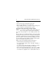
Barracuda 4LP Installation Guide, Rev. B 1 Preface This manual contains information for users of the Seagate® Barracuda 4LP SCSI disc drives. It provides support services, performance specifications, and initial setup information. Additional information is available in the Barracuda 4LP Product Manual (part number 77767491). Contact your Seagate sales representative if you need to order this publication. Electrostatic discharge protection Caution.
2 Barracuda 4LP Installation Guide, Rev. B • Turn off the power before removing or installing the DC power cable. • Do not remove any circuit boards from the drive. • Never use an ohmmeter on any circuit boards. • When installing the drive on a carrier or tray, discharge the carrier or tray prior to inserting it into the system. Important safety information and precautions Caution. Use forced-air ventilation when bench-testing the drive to ensure proper cooling of drive components.
Barracuda 4LP Installation Guide, Rev. B • • • • 3 stacked vertically, pay special attention to the top where temperatures are usually highest. Follow the precautions listed above in “Electrostatic discharge protection.” Do not remove any circuit boards from the drive. Return the entire drive for depot repair if any circuit board is defective. Removal of circuit boards by personnel not performing depot repair will damage components and may void the warranty.
4 Barracuda 4LP Installation Guide, Rev. B This unit is a component part and as such is not meant to comply with FCC or similar national requirements as a stand-alone unit. Engineering radiated emissions test results are available through the Seagate Safety Department to assist the subsystem designer. Wichtige Sicherheitshinweise Vorsicht. Beim Testen des Laufwerks auf dem Prüftisch ist Fremdbelüftung vorzusehen, um eine ausreichende Kühlung der Laufwerkkomponenten sicherzustellen.
Barracuda 4LP Installation Guide, Rev. B 5 Beachten Sie in jedem Fall die folgenden Warn-und Vorsichtshinweise: • Beachten Sie alle Warn- und Vorsichtshinweise in diesem Handbuch. • Treffen Sie beim Betrieb, bei der Installation oder bei der Entfernung der Einheit angemessene Sicherheitsvorkehrungen. • Wenn eine Einheit unter Spannung steht, gehen Sie bei der Fehlerdiagnose besonders vorsichtig vor. Schalten Sie die Einheit aus, bevor Sie mit den Installations-und Entfernungsarbeiten beginnen.
6 Barracuda 4LP Installation Guide, Rev. B • Die vormontierte Kopf- und Festplatteneinheit (HDA) nicht aus dem Laufwerk nehmen! Falls die HDA beschädigt ist, schicken Sie das gesamte Laufwerk zur Reparatur ein. • Die HDA ist nicht vor Ort reparierbar und darf nicht auseinandergenommen werden! Öffnen der versiegelten HDA durch andere Personen als die für die werkseitige Reparatur zuständigen hat eine Beschädigung der Komponenten und Erlöschen des Garantieanspruchs zur Folge.
Barracuda 4LP Installation Guide, Rev. B 7 magnetische Strahlung sind für Designer von Untersystemen auf Anfrage von der Seagate-Sicherheitsabteilung erhältlich. European Union Compliance If this model has the CE Marking, it complies with the European Union requirements of the Electromagnetic Compatibility Directive 89/336/EEC of 03 May 1989 as amended by Directive 92/ 31/EEC of 28 April 1992 and Directive 93/68/EEC of 22 July 1993.
8 Barracuda 4LP Installation Guide, Rev. B Technical support services If you need assistance installing your drive, consult your dealer. Dealers are familiar with their unique system configurations and can help you with system conflicts and other technical issues. If you need additional assistance with your Seagate® drive or other Seagate products, use one of the Seagate technical support services listed below.
Barracuda 4LP Installation Guide, Rev. B 9 SeaBOARD® SeaBOARD is a computer bulletin board system (BBS) that contains information about Seagate’s disc and tape drive products and is available 24 hours daily. Set your communications software to eight data bits, no parity, and one stop bit (8-N-1). SeaBOARD phone numbers are listed in the following table.
10 Barracuda 4LP Installation Guide, Rev. B Seagate Technology FAX services SeaFAX® You can use a touch-tone telephone to access Seagate’s automated FAX system to receive technical support information by return FAX. This service is available 24 hours daily. Location United States England Australia Telephone number 1-800-SEAGATE or 408-456-4496 44-1628-894084 61-2-9756-5170 Seagate technical support FAX You can FAX questions or comments to technical support specialists 24 hours daily.
Barracuda 4LP Installation Guide, Rev. B 11 Before calling, note your system configuration and drive model number (STxxxx). There are several technical support phone numbers available for various Seagate products. Location United States England France Germany Australia Singapore Hong Kong Taiwan Korea Telephone number Please dial 1-800-SEAGATE for the specific product telephone number. (6:00 A.M. to 11:15 A.M., 12:30 P.M. to 5:00 P.M., M–F) 44-1628-894083 (10:00 A.M. to 1:00 P.M., 2:00 P.M. to 5:00 P.
12 Barracuda 4LP Installation Guide, Rev. B General description Barracuda 4LP SCSI disc drives are high-speed, random-access digital-data storage devices. The drive is a component for installation in an enclosure designed for the drive. This is often a rack within the system or an external enclosure designed to house one or more disc drives or other peripheral units.
Barracuda 4LP Installation Guide, Rev. B Table 1. Interface 13 Drive characteristics UltraSCSI [1] Capacity ST34371 ST32171 ST34571 ST32271 Formatted [2] 4.35 Gbyte [2] 2.16 Gbyte [2] 4.55 Gbyte [2] 2.26 Gbyte [2] Recording Cylinders (user) Read/write data heads ST32171/ST32271 ST34371/ST34571 5 10 Access time [3] Average read Average write 9.4 msec 10.4 msec Disk rotation RPM Average latency 7,200 r/min 4.17 msec Unformatted 5.31 Gbyte 2.65 Gbyte 5.54 Gbyte 2.
14 Barracuda 4LP Installation Guide, Rev. B [2] Standard factory units are formatted 512 data bytes per sector with sparing equivalent to eighty spare sectors per eight cylinder region. Spares are located at the end of each sparing region. [3] Includes controller overhead. Table 2a. DC power requirements (Amps) Voltage Regulation [5] Max. operating current DC3σ [1] Avg. idle current DCX [1] Max.
Barracuda 4LP Installation Guide, Rev. B 15 Table 2b. DC power requirements (Amps) Voltage Regulation [5] Max. operating current DC3σ [1] Avg. idle current DCX [1] Max. starting current (peak DC) DC3σ [3] (peak AC) AC3σ [3] Delayed motor start (max) DC3σ [1][4] Peak operating current Typical DCX [1] [6] Maximum DC3σ [1] Maximum (peak) 3σ ST32171/ST32271 N/W/WC WD/DC Single-ended Differential +5V +12V +5V +12V ±5% ±5% [2] ±5% ±5%[2] 0.81 0.46 0.85 0.52 1.21 0.70 0.85 0.52 0.78 2.00 3.1 1.1 2.00 3.
16 Barracuda 4LP Installation Guide, Rev. B [5] See “Conducted noise immunity” in the Barracuda 4LP Product Manual. The specified voltage tolerance is inclusive of ripple, noise, and transient response. [6] Operating condition is defined as random seek read operations with a block count of 64. General Notes from Tables 2a and 2b. 1. Minimum current loading for each supply voltage is not less than 4% of the maximum operating current shown. 2. 3. Use separate ground returns for +5V and +12V supplies.
Barracuda 4LP Installation Guide, Rev. B 17 Initial setup information The general information beginning on this page applies to all of the Barracuda 4LP drive models. After reading the general information topics, refer to the appropriate drive-specific section listed below for additional information about configuring and installing your particular model.
18 Barracuda 4LP Installation Guide, Rev. B SCSI ID jumpers Each device on the SCSI chain must have a unique SCSI ID. The host system’s SCSI controller usually uses the ID that has the highest priority interrupt in the SCSI I/O system. This is always ID7. ID0 is lowest priority in an 8-bit I/O system. ID8 is lowest priority in a 16-bit I/O system. The lower priority SCSI IDs are normally used for other SCSI devices such as this Barracuda disc drive. Note.
Barracuda 4LP Installation Guide, Rev. B 19 the case, change the ID so that each device on the SCSI chain has its own unique ID. Also check your system or controller user’s manual to ensure that you have not violated its SCSI ID numbering recommendations. Drive termination If you are installing a Barracuda drive in a system that has other SCSI devices installed, terminate only the end devices on the SCSI chain.
20 Barracuda 4LP Installation Guide, Rev. B For information about how to terminate your drive, refer to the appropriate drive-specific section. Internal SCSI cable Internal SCSI device Internal SCSI device Controller Terminate Internal SCSI cable Internal SCSI device Internal SCSI device Controller External SCSI cable External SCSI device External SCSI device Terminate Figure 2.
Barracuda 4LP Installation Guide, Rev. B 21 Figures 3a, 3b, 3c, and 3d show typical drive connections. The following table lists the maximum cable lengths and number of devices with single-ended I/O circuits allowed on a daisy-chain cable for <10 and <20 M transfers/sec I/O data transfer rates. Table 4. Cable characteristics for single-ended circuits I/O transfer rate Maximum number of devices on line Maximum cable length allowed <10 M transfers/s 8 (reg. SCSI bus) 6 meters (19.7 ft.
22 Barracuda 4LP Installation Guide, Rev. B HDA Pin 1 Figure 3a. Fifty pin I/O connection to drive HDA Pin 1 Figure 3b.
Barracuda 4LP Installation Guide, Rev. B 23 “N” Model Drive SCSI ID X (or last drive) [1] Additional SCSI devices SCSI ID 1 Pin 1 (check your adapter for Pin 1 location) SCSI ID 7 SCSI ID 0 Host Adapter PCB [1] “X” means up to 6 or the maximum allowable number of devices on the SCSI bus. See Table 4 and system documentation. Figure 3c.
24 Barracuda 4LP Installation Guide, Rev. B “WD” Model Drive [1] “W” Model Drive [1] [3] SCSI ID X (or last drive) [2] Additional SCSI devices SCSI ID 1 Pin 1 (check your adapter for Pin 1 location) SCSI ID 7 SCSI ID 0 Host Adapter PCB [1] Do not mix “W” and “WD” model drives on the daisy chain. [2] “X” means up to 15 or the maximum allowable number of devices on the SCSI bus. See Table 4 and system documentation. [3] External terminator. Figure 3d.
Barracuda 4LP Installation Guide, Rev. B 25 Note. This drive model plugs directly into a backplane connector and therefore uses no cables. Figure 3e.
26 Barracuda 4LP Installation Guide, Rev. B Providing adequate cooling The enclosure design must ensure adequate cooling for the drive. The maximum ambient temperature is 50°C. The drive’s product manual (77767491) describes how to evaluate the air-flow design. The evaluation consists of ensuring that the case temperature of certain critical components remains within acceptable limits during drive operation.
Barracuda 4LP Installation Guide, Rev. B 27 Kühlung des Systems Die Gehäusekonstruktion muß eine ausreichende Kühlung des Laufwerkes gewährleisten. Die Umgebungstemperatur darf maximal 50°C betragen. Die Produkthandbuch Barracuda 4LP (Dokument 77767491) enthalten Anweisungen zur Beurteilung der Luftstromkonstruktion. Die Beurteilung muß sicherstellen, daß sich die Gehäusetemperatur bestimmter kritischer Komponenten bei Laufwerkbetrieb innerhalb zugelassener Grenzen hält.
28 Barracuda 4LP Installation Guide, Rev. B . Above unit Über der Einheit Note. Air flows in the direction shown (back to front) or in reverse direction (front to back) Under unit Unter der Einheit Hinweis. Luftstrom in der angezeigten Richtung (von vorne nach hinten) oder in umgekehrter Richtung (von hinten nach vorne) Above unit Über der Einheit Note. Air flows in the direction shown or in reverse direction (side to side) Hinweis.
Barracuda 4LP Installation Guide, Rev. B 29 Mounting the drive and connecting cables Do not touch the connector pins or any components on the control board without observing static-discharge precautions. Always handle the drive by the frame only. The drive may be mounted in any orientation (horizontally, vertically, and any combination thereof); however, you must ensure that the drive receives adequate air flow for cooling. 1. Mount the drive to the host system’s chassis using four 6-32 UNC screws.
30 Barracuda 4LP Installation Guide, Rev. B 1. Befestigen Sie das Laufwerk mit vier 6-32-UNC-Schrauben am Gehäuse des Host-Systems. Die beiden Seiten des Laufwerkes sind mit jeweils zwei Befestigungslöchern versehen, die Unterseite des Laufwerkes weist vier weitere Befestigungslöcher auf. Gemessen von der Außenfläche des Gehäuses dürfen die Schrauben maximal 3,81 mm in die Befestigungslöcher des Gehüuses hineinragen. Die Schrauben müssen gleichmäßig, jedoch nicht zu fest, angezogen werden.
Barracuda 4LP Installation Guide, Rev. B 31 defined in IEC 950. Figure 5 provides the pin information for the DC power connector. To connect the DC power cable to the drive, simply insert the cable end into the drive’s DC power connector. 4. Schließen Sie das SCSI-Kabel an den SCSI-Steckverbinder des Laufwerkes an. Das Kabel darf nicht gedehnt oder gedrückt werden und es darf den Luftstrom zur Kühlung des Systems nicht behindern.
32 Barracuda 4LP Installation Guide, Rev. B Note. Signal ground on the power control board (PCB) and the head and disc assembly (HDA) are connected together in this drive and you cannot separate them. The equipment in which you have mounted the drive is connected directly to the HDA and PCB without electrically isolating shock mounts. Maximizing the conductive contact area between HDA ground and system ground may reduce radiated emissions.
Barracuda 4LP Installation Guide, Rev. B 33 tem einbauen. Die daraus u.U. resultierende verstärkte elektromagnetische Strahlung fällt in den Zuständigkeitsbereich des Systemdesigners. 5. Replace the host system’s cover. 5. Setzen Sie das Gehäuseoberteil des Host-Systems wieder auf.
34 Barracuda 4LP Installation Guide, Rev. B [4] C [3] G L D [1] F E A Notes: [1] Mounting holes three on each side, 6-32 UNC. Max screw length into side of drive 0.15 in. (3.81 mm). Screw tightening torque 6.0 in-lb (.675 NM) max with minimum thread engagement of 0.12 in. (3.05 mm). [2] Mounting holes four on bottom, 6-32 UNC. Max screw length into bottom of drive 0.20 in. (5.08 mm). Screw tightening torque 6.0 in-lb (.675 NM) max with minimum thread engagement of 0.12 in. (3.05 mm).
Barracuda 4LP Installation Guide, Rev. B 35 Formatting the drive Warning. Formatting a drive erases all user data. Be sure that you understand this principle before formatting any hard disc drive. It is not necessary to format a drive that previously has been used to store data, unless your intention is to erase all user data. Note. Seagate is not responsible for lost user data. 1. 2. 3. Turn on DC power.
36 Barracuda 4LP Installation Guide, Rev. B N drives Setting the SCSI ID N/ND jumpers drives section Use the J6 connector to set the SCSI ID (see Figure 7). To change the SCSI ID, install jumpers on the appropriate pins as shown in the illustration. Drive Front Jumper Plug (enlarged to show detail) Pin 1 J6 Reserved SCSI ID = 0 L R R E E EA A A D S S 2 1 0 (default) SCSI ID = 1 SCSI ID = 2 SCSI ID = 3 SCSI ID = 4 SCSI ID = 5 SCSI ID = 6 SCSI ID = 7 Figure 7.
Barracuda 4LP Installation Guide, Rev. B 37 N drives Terminating the drive “N” model drives are terminated with permanently mounted IC active terminators. If you install one of these drives and it is not on the end of the SCSI bus, disable the terminators by removing the jumper “TE” from pins 15 and 16 of connector J2 (see Figure 8). If you install the drive on the end of the SCSI bus, enable termination by installing a jumper on pins 15 and 16 of connector J2.
38 Barracuda 4LP Installation Guide, Rev. B N drives Terminator power There are three possible terminator power (TP) configurations for “N” model drives (see Figure 9). You will not normally need to change this option and can leave the drive configured as it was shipped from the factory. Pin 1 J2 “N” model drives Term. Power from Drive R T D MW P E T T E S E P D S P P (default) Term. Power to SCSI Bus Term.
Barracuda 4LP Installation Guide, Rev. B 39 N drives Other applicable jumper options Several other jumper options are available as illustrated. Drive with HDA up, PCB down, viewed from front J2 Pin 1 HDA Delay Motor Start option (valid only if the Enable Motor Start jumper is not connected) J6 Reserved L R R E E EA A A D S S 2 1 0 Reserved 11 Remote LED 12 CATH Shipped with cover installed. Do not remove. Do not install jumpers on these four positions.
40 Barracuda 4LP Installation Guide, Rev. B W/WD drives Setting the SCSI W/WD ID jumpers drives section Use the J6 jumper block to set the SCSI ID (Figure 11). To change the SCSI ID, install jumpers on the appropriate pins as shown in the illustration. Optional connections to switching circuits in host equipment are provided on J1 auxiliary to set the SCSI ID (see Figure 12).
Barracuda 4LP Installation Guide, Rev. B 41 W/WD drives 68 Pin SCSI I/O +5V Connector Ground Pin 1 J1-Auxiliary Pin 1A 4P J1-DC Power 3P2P Drive HDA Rear 1P J1 (default) SCSI ID = 0 PCB SCSI ID = 1 SCSI ID = 2 SCSI ID = 3 SCSI ID = 4 SCSI ID = 5 SCSI ID = 6 For ID selection use jumpers as shown or connect a cable for remote switching as shown below.
42 Barracuda 4LP Installation Guide, Rev. B W/WD drives Terminating the drive “W” model drives are terminated with permanently mounted IC active terminators. If you install one of these drives and it is not on the end of the SCSI bus, disable the terminators by removing the jumper “TE” from pins 15 and 16 of connector J2. If you install the drive on the end of the SCSI bus, enable termination by installing a jumper on pins 15 and 16 of connector J2 (see Figure 13). Note.
Barracuda 4LP Installation Guide, Rev. B 43 W/WD drives Terminator power There are three possible terminator power (TP) configurations for “W” model drives (see Figure 14). You will not normally need to change this option and can leave the drive configured as it was shipped from the factory. There are two possible terminator power (TP) configurations for “WD” model drives (see Figure 14). Pin 1 J2 “W” model drives Term. Power from Drive R T D MW P E T T E S E P D S P P (default) Term.
44 Barracuda 4LP Installation Guide, Rev. B W/WD drives Other applicable jumper options Other option jumpers are available as illustrated below. Drive with HDA up, PCB down, viewed from front J2 Pin 1 HDA Delay Motor Start option (valid only if the Enable Motor Start jumper is not connected) J6 Reserved L R E EA A A A D S 3 2 1 0 Reserved 11 Remote LED 12 CATH Shipped with cover installed. Do not remove. Do not install jumpers on these four positions.
Barracuda 4LP Installation Guide, Rev. B 45 WC/DC drives Setting the SCSIWC/DC ID jumpers drives section The SCSI ID for “WC” and “DC” model drives is normally set over the SCSI bus by the host system using connector contacts 39 (ID0), 40 (ID2), 79 (ID1), and 80 (ID3). Users need not install jumpers to select SCSI ID. Terminating the drive “WC” and “DC” model drives do not have internal terminators or any other way of adding internal termination to the drive.
46 Barracuda 4LP Installation Guide, Rev. B WC/DC drives Applicable jumper options Option jumpers are available as illustrated below. Pin 1 J2 Delay Motor Start option The host system has complete control over motor start functions. Do not install a jumper on these pins. R T D MW P E T T E S E P D S P P Enable Motor Start option The host system has complete control over motor start functions. Do not install a jumper on these pins.
Seagate Technology, Inc. 920 Disc Drive, Scotts Valley, CA 95066-4544, USA Publication Number: 77767492, Rev.