................................................. Barracuda 4LP Family: ................................................. ST34371N/W/WD/WC/DC ................................................. ST32171N/W/WD/WC/DC ................................................. ST34571N/W/WD/WC/DC ................................................. ST32271N/W/WD/WC/DC ................................................. ................................................. Product Manual, Volume 1 .............................
................................................. Barracuda 4LP Family: ................................................. ST34371N/W/WD/WC/DC ................................................. ST32171N/W/WD/WC/DC ................................................. ST34571N/W/WD/WC/DC ................................................. ST32271N/W/WD/WC/DC ................................................. ................................................. Product Manual, Volume 1 .............................
© 1998 Seagate Technology, Inc. All rights reserved Publication number: 77767491, Rev. D February 1998 Seagate, Seagate Technology, and the Seagate logo are registered trademarks of Seagate Technology, Inc. Barracuda, SeaFAX, SeaFONE, SeaNET, SeaTDD, and SeaBOARD are either trademarks or registered trademarks of Seagate Technology, Inc. or one of its subsidiaries. All other trademarks or registered trademarks are the property of their respective owners.
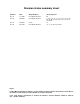
Revision status summary sheet Revision Date Writer/Engineer Sheets Affected Rev. A Rev. B 11/18/96 06/09/97 D. Ashby/B. Norman D. Ashby/B. Norman Rev. C Rev. D 07/29/97 02/13/98 K. Tan D. Ashby/B. Norman All 3, 4, 5, 7, 8, 10, 11, 15, 17, 19, 24, 31, 33, 34, 36, 45, 53, 56, 57, 67, 68, 71, 72, 73, 75 and 76. 10. 15, 17, 21, 29, 75, and 76. Notice.
Barracuda 4LP Product Manual, Rev. D vii Contents 1.0 Scope . . . . . . . . . . . . . . . . . . . . . . . . . . . . . . . . . . . . . . . . . . . . . . . . . . . . . . . . . . . . . . . . . . . . . . . . . . 1 2.0 Applicable standards and reference documentation. . . . . . . . . . . . . . . . . . . . . . . . . . . . . . . . . . . . 2.1 Standards . . . . . . . . . . . . . . . . . . . . . . . . . . . . . . . . . . . . . . . . . . . . . . . . . . . . . . . . . . . . . . . . . 2.1.
viii Barracuda 4LP Product Manual, Rev. D 6.5 6.4.3 Effective altitude (sea level) . . . . . . . . . . . . . . . . . . . . . . . . . . . . . . . . . . . . . . . . . . .23 6.4.4 Shock and vibration . . . . . . . . . . . . . . . . . . . . . . . . . . . . . . . . . . . . . . . . . . . . . . . . .23 6.4.5 Air cleanliness . . . . . . . . . . . . . . . . . . . . . . . . . . . . . . . . . . . . . . . . . . . . . . . . . . . . .25 6.4.6 Acoustics . . . . . . . . . . . . . . . . . . . . . . . . . . . . . . . . .
Barracuda 4LP Product Manual, Rev. D ix Figures Figure 1. Figure 2. Figure 3. Figure 4. Figure 5. Figure 6a. Figure 6b. Figure 6c. Figure 7a. Figure 7b. Figure 7c. Figure 7d. Figure 7e. Figure 8. Figure 9a. Figure 9b. Figure 9c. Figure 10. Figure 11a. Figure 11b. Figure 11c. Figure 12. Figure 13. Barracuda 4LP family drive . . . . . . . . . . . . . . . . . . . . . . . . . . . . . . . . . . . . . . . . . . . . . . . . . . . 1 Barracuda 4LP family drive . . . . . . . . . . . . . . . . . . . . . . . . . . .
Barracuda 4LP Product Manual, Rev. D 1.0 1 Scope This manual describes the Seagate Technology®, Inc. Barracuda 4LP™ disc drives. Barracuda 4LP drives support the small computer system interface (SCSI) as described in the ANSI SCSI, SCSI-2, and SCSI-3 (Fast-20) interface specifications to the extent described in this manual. The SCSI Interface Product Manual (part number 77738479) described general SCSI interface characteristics of this and other families of Seagate drives.
Barracuda 4LP Product Manual, Rev. D 2.0 3 Applicable standards and reference documentation The drive has been developed as a system peripheral to the highest standards of design and construction. The drive depends upon its host equipment to provide adequate power and environment in order to achieve optimum performance and compliance with applicable industry and governmental regulations.
4 Barracuda 4LP Product Manual, Rev. D Australian C-Tick If this model has the C-Tick Marking it complies with the Australia/New Zealand Standard AS/NZS3548 1995 and meets the Electromagnetic Compatibility (EMC) Framework requirements of Australia’s Spectrum Management Agency (SMA). 2.3 Reference documents Installation Guide Seagate P/N 77767492 SCSI Interface Manual Seagate P/N 77738479 ANSI small computer system interface (SCSI) document numbers: X3.131-1994 SCSI-2 X3T10/855D rev.
Barracuda 4LP Product Manual, Rev. D 3.0 5 General description Barracuda 4LP drives combine magnetoresistive (MR) heads, partial response/maximum likelihood (PRML) read channel electronics, embedded servo technology, and a SCSI-3 (Fast-20) interface to provide high performance, high capacity data storage for a variety of systems including engineering workstations, network servers, mainframes, and supercomputers. Fast-20 (also known as Ultra SCSI) is a negotiated transfer rate.
6 Barracuda 4LP Product Manual, Rev. D The drive’s interface supports multiple initiators, disconnect/reconnect, self-configuring host software, and automatic features that relieve the host from the necessity of knowing the physical characteristics of the targets (logical block addressing is used). The head and disc assembly (HDA) is sealed at the factory. Air circulates within the HDA through a nonreplaceable filter to maintain a contamination-free HDA environment.
Barracuda 4LP Product Manual, Rev. D 3.
8 Barracuda 4LP Product Manual, Rev. D 3.5 Unformatted and formatted capacities Formatted capacity depends on the number of spare reallocation sectors reserved and the number of bytes per sector. The following table shows the standard OEM model capacities: ST34371 ST32171 ST34571 ST32271 Formatted [1] Data Block Size 512 Byte/Sector Unformatted 4.35 GB [2] 2.16 GB [2] 4.55 GB [2] 2.26 GB [2] 5.31 GB 2.65 GB 5.54 GB 2.77 GB Notes. [1] [2] 3.6 Sector size selectable at format time.
Barracuda 4LP Product Manual, Rev. D 9 4.0 Performance characteristics 4.1 Internal drive characteristics (transparent to user) Drive Capacity Read/Write Heads Bytes/Track Bytes/Surface Tracks/Surface, Total Tracks/Inch Peak Bits/Inch Internal Data Rate Disc Rotational Speed Average Rotational Latency 4.2 ST34371 ST32171 ST34571 ST32271 5.31 10 102,500 531 5,178 5,555 123,000 80-122 7,200 4.17 2.65 5 102,500 531 5,178 5,555 123,000 80-122 7,200 4.17 5.
10 Barracuda 4LP Product Manual, Rev. D 4.2.2 Format command execution time (minutes) [1]* ST34371/ST34571 ST32171/ST32271 95 65 50 35 Maximum (with verify) Maximum (no verify) 4.2.3 Generalized performance characteristics Minimum sector interleave 1 to 1 Data buffer transfer rate to/from disc media (one 512-byte sector): Min. [4]* Avg. [4] 9.5 MByte/sec 13.2 MByte/sec Max. [4] 15.0 MByte/sec Data buffer transfer rate to/from disc media: (< 1 track): Min.
Barracuda 4LP Product Manual, Rev. D 11 Notes for Section 4.2. [1] [2] [3] [4] [5] [6] [7] [8] 4.3 Execution time measured from receipt of the last Byte of the Command Descriptor Block (CDB) to the request for a Status Byte Transfer to the Initiator (excluding connect/disconnect). Maximum times are specified over the worst case conditions of temperature, voltage margins and drive orientation.
12 Barracuda 4LP Product Manual, Rev. D The following is a simplified description of a read operation with cache operation enabled: Case A - A Read command is received and the first logical block (LB) is already in cache: 1. Drive transfers to the initiator the first LB requested plus all subsequent contiguous LB’s that are already in the cache. This data may be in multiple segments. 2.
Barracuda 4LP Product Manual, Rev. D 13 During a prefetch operation, the drive crosses a cylinder boundary to fetch more data only if the Discontinuity (DISC) bit is set to one in bit 4 of byte 2 of Mode parameters page 08h. Whenever prefetch (read look-ahead) is enabled (enabled by DRA = 0), it operates under the control of ARLA (Adaptive Read Look-Ahead).
Barracuda 4LP Product Manual, Rev. D 5.0 15 Reliability specifications The following reliability specifications assume correct host/drive operational interface, including all interface timings, power supply voltages, environmental requirements and drive mounting constraints (see Section 8.4).
16 5.1.4 Barracuda 4LP Product Manual, Rev. D Seek errors A seek error is defined as a failure of the drive to position the heads to the addressed track. There shall be no more than one recoverable seek errors in 10 7 physical seek operations. After detecting an initial seek error, the drive automatically performs an error recovery process. If the error recovery process fails, a seek positioning error (15h) is reported with a Medium error (3h) or Hardware error (4h) reported in the Sense Key.
Barracuda 4LP Product Manual, Rev. D 5.2.6 17 Hot plugging Barracuda 4LP disc drives Caution: Hot-plug drives are not designed for simultaneous power disconnection and physical removal. During power-up and power-down periods, the hot SCSI connect/disconnect capability does not produce glitches or any corruptions on an active SCSI bus. Barracuda 4LP drives conform to the SCSI-3 standard requirements for glitch-free power-on and power-off.
18 Barracuda 4LP Product Manual, Rev. D Product repair and return information Seagate customer service centers are the only facilities authorized to service Seagate drives. Seagate does not sanction any third-party repair facilities. Any unauthorized repair or tampering with the factory-seal voids the warranty.
Barracuda 4LP Product Manual, Rev. D 6.0 19 Physical/electrical specifications This section provides information relating to the physical and electrical characteristics of the Barracuda 4LP drive. 6.1 AC power requirements None 6.2 DC power requirements The voltage and current requirements for a single drive are shown in the following table. Values indicated apply at the drive power connector. The single ended power requirements includes the internal disc drive SCSI I/O termination.
20 Barracuda 4LP Product Manual, Rev. D 6.2.1 Conducted noise immunity Noise is specified as a periodic and random distribution of frequencies covering a band from DC to 10 mHz. Maximum allowed noise values given below are peak to peak measurements and apply at the drive power connector. +5 V = +12 V = 150 mV pp from 0 to 100 kHz and 100 mV pp from 100 kHz to 10 MHz. 150 mV pp from 0 to 100 kHz and 100 mV pp from 100 kHz to 10 MHz. 6.2.2 Power sequencing The drive does not require power sequencing.
Barracuda 4LP Product Manual, Rev. D 6.3 21 Power dissipation For drives with single ended interface circuits, typical operating random read power dissipation is 12.9 watts (44 BTUs per hour) of DC power average at nominal voltages. Typical power dissipation under idle conditions is 8.8 watts (30 BTUs per hour). For drives with differential interface circuits, typical operating random read power dissipation is 14.4 watts (49 BTUs per hour) of DC power average at nominal voltages.
22 Barracuda 4LP Product Manual, Rev. D Model “WC/DC” PCB* U17 U8 U13 U5 U6 U7 U14 U2 U16 U1 U19 HDA Temp. Check Point .5 U15 " U4 J1 PCB 3 Model “N” PCB * Model “W/WD” PCB* U17 U17 U8 U13 U8 U5 U13 U6 U7 U14 U5 U6 U7 U14 U2 U2 U16 U16 U1 U1 U19 U19 U15 U15 U4 J1 U4 J1 PCB 1 PCB 2 * Bottom side of PCB Figure 4. Locations of PCB components listed in Table 3 6.4.2 Relative humidity The values below assume that no condensation on the drive occurs. a.
Barracuda 4LP Product Manual, Rev. D 6.4.3 23 Effective altitude (sea level) a. Operating –1,000 to +10,000 feet (–305 to +3,048 meters) b. Non-Operating –1,000 to +40,000 feet (–305 to +12,210 meters) 6.4.4 Shock and vibration Shock and vibration limits specified in this document are measured directly on the drive chassis.
24 Barracuda 4LP Product Manual, Rev. D Z X Y Z Y X Note. Use four screws (two per side) when using the mounting holes located on the sides of the drive. See Section 8.4 when using the mounting holes located on the bottom of the drive. Figure 5.
Barracuda 4LP Product Manual, Rev. D 6.4.4.2 25 Vibration a. Operating - normal The drive as installed for normal operation, shall comply with the complete specified performance while subjected to continuous vibration not exceeding 5-350 Hz @ 0.5 g Vibration may be applied in the X, Y, or Z axis. b. Operating - abnormal 5-350 Hz @ 0.75 g (X, Y, or Z axis) c. Non-operating The limits of non-operating vibration shall apply to all conditions of handling and transportation.
26 Barracuda 4LP Product Manual, Rev. D 6.5 Mechanical specifications The following nominal dimensions are exclusive of the decorative front panel accessory. However, dimensions of the front panel are shown in figure below. Refer to Figures 6a, 6b, and 6c for detailed mounting configuration dimensions. See Section 8.4, “Drive mounting.” Height: Width: Depth: Weight: 1.00 in 4.00 in 5.74 in 1.5 pounds 25.4 101.6 145.8 0.
Barracuda 4LP Product Manual, Rev. D 27 [4] C [3] G L D [1] F E A Notes: [1] Mounting holes three on each side, 6-32 UNC. Max screw length into side of drive 0.15 in. (3.81 mm). Screw tightening torque 6.0 in-lb (.675 NM) max with minimum thread engagement of 0.12 in. (3.05 mm). [2] Mounting holes four on bottom, 6-32 UNC. Max screw length into bottom of drive 0.15 in. (3.81 mm). Screw tightening torque 6.0 in-lb (.675 NM) max with minimum thread engagement of 0.12 in. (3.05 mm).
28 Barracuda 4LP Product Manual, Rev. D [4] C [3] G L D [1] F E A Notes: [1] Mounting holes three on each side, 6-32 UNC. Max screw length into side of drive 0.15 in. (3.81 mm). Screw tightening torque 6.0 in-lb (.675 NM) max with minimum thread engagement of 0.12 in. (3.05 mm). [2] Mounting holes four on bottom, 6-32 UNC. Max screw length into bottom of drive 0.15 in. (3.81 mm). Screw tightening torque 6.0 inlb (.675 NM) max with minimum thread engagement of 0.12 in. (3.05 mm).
Barracuda 4LP Product Manual, Rev. D 7.0 29 Defect and error management The drive, as delivered, complies with this specification. The read error rate and specified storage capacity are not dependent upon use of defect management routines by the host (initiator). Defect and error management in the SCSI system involves the drive internal defect/error management and SCSI systems error considerations (errors in communications between Initiator and the drive).
Barracuda 4LP Product Manual, Rev. D 8.0 31 Installation The first thing to do when installing a drive is to set the drive ID (select) on the SCSI bus and set up certain operating options. This is usually done by installing small shorting jumpers on the pins of connectors J2 and J6 on the PCB (or J1-Auxiliary on the “W” and “WD” models), or via the drive to host I/O signals on “WC” and “DC” models. Some users connect cables to J6 or J1-Auxiliary and perform the set-up using remote switches.
32 Barracuda 4LP Product Manual, Rev. D Drive Front Jumper Plug (enlarged to show detail) Pin 1 J6 L R R Reserved E E E A A A D S S 2 1 0 SCSI ID = 0 (default) SCSI ID = 1 SCSI ID = 2 SCSI ID = 3 SCSI ID = 4 SCSI ID = 5 SCSI ID = 6 SCSI ID = 7 [3] [4] Host Alternate Usage Plug: Reserved Pins +5V [6] 11 9 7 5 3 1 6 4 2 Ground Shipped with cover installed. Do not install jumpers; retain cover. Optional connections to switching circuits in host equipment to establish drive ID.
Barracuda 4LP Product Manual, Rev. D 33 Drive Front Jumper Plug (enlarged to show detail) Pin 1 J6 [1] L R E E D S Reserved A3 A2 A1A0 SCSI ID = 0 (default) SCSI ID = 1 SCSI ID = 2 SCSI ID = 3 SCSI ID = 4 SCSI ID = 5 SCSI ID = 6 [4] SCSI ID = 7 SCSI ID = 8 SCSI ID = 9 SCSI ID = 10 SCSI ID = 11 SCSI ID = 12 SCSI ID = 13 SCSI ID = 14 SCSI ID = 15 [3] [4] Host Alternate Usage Plug: Reserved Pins 11 9 7 5 3 1 8 +5V Ground [6] Drive Activity LED [8] 6 4 2 Shipped with cover installed.
34 Barracuda 4LP Product Manual, Rev. D Drive HDA (rear view, PCB facing downward) Pin 1 +5V Ground J1-Auxiliary [1] [2] Pin 1A 4P [2] Pin 12A 68 Pin SCSI I/O Connector J1 SCSI ID = 0 3P 2P 1P J1-DC Power (default) PCB SCSI ID = 1 SCSI ID = 2 SCSI ID = 3 SCSI ID = 4 SCSI ID = 5 SCSI ID = 6 For ID selection use jumpers as shown or connect a cable for remote switching as shown below.
Barracuda 4LP Product Manual, Rev. D 35 J2 Jumper Positions Caution: RT T T D MW P E P P E S EP DS 2 1 (default - models “N” and “W” only) Terminator Enable Delay Motor Start Do not use J2 jumper plugs on J6 or J1Auxiliary, as the internal contacts will be deformed and can not be used on J2 without them falling off. Pin 1 Enable Motor Start Write Protect Parity Disable (default - models “N” and “W” only) Term. Power from Drive *Additional notes on these Term.
36 Barracuda 4LP Product Manual, Rev. D 8.1.1 Notes for Figures 7a, 7b, 7c, 7d, and 7e. [1] Notes explaining the functions of the various jumpers on jumper header connectors J2, J1-Auxiliary and J6 are given here and in Section 8.1.2. The term “default” means as standard OEM units are configured with a jumper on those positions when shipped from factory. “Off” means no jumper is installed; “On” means a jumper is installed. OFF or ON underlined is factory default condition.
Barracuda 4LP Product Manual, Rev.
38 Barracuda 4LP Product Manual, Rev. D 8.1.2 Function description J2 Jumper Installation TE On Jumper Function Description (Applies only to “N” and “W” models) With the jumper installed, the On-board (non-removable) terminator circuits are enabled (connected to the I/O lines). Default is jumper installed. Terminator circuits not enabled (not connected to I/O lines). Off DS Off Off On ME Off On Off On On (Applies to all models) Spindle starts immediately after power up - Default setting.
Barracuda 4LP Product Manual, Rev. D 8.2 39 Drive orientation The balanced rotary arm actuator design of the drive allows it to be mounted in any orientation. All drive performance characterization, however, has been done with the drive in horizontal (discs level) and vertical (drive on its side) orientations, and these are the two preferred mounting orientations. 8.
40 8.4 Barracuda 4LP Product Manual, Rev. D Drive mounting When mounting the drive using the bottom holes (x-y plane in Figure 5) care must be taken to ensure that the drive is not physically distorted due to a stiff non-flat mounting surface. The allowable mounting surface stiffness is 80 lb/in (14.0 N/mm). The following equation and paragraph define the allowable mounting surface stiffness: F K = --- = 80lb/in (14.
Barracuda 4LP Product Manual, Rev. D 9.0 41 Interface requirements This section describes Barracuda 4LP interface requirements. 9.1 General description This section partially describes the interface requirements as implemented on the drives. The major portion of the interface requirements /implementation is described in the Seagate SCSI Interface Product Manual, P/N 77738479.
42 9.3 Barracuda 4LP Product Manual, Rev. D SCSI interface commands supported Table 6 following lists the SCSI interface commands that are supported in the SCSI-2, and SCSI-3 modes of the drive. Barracuda 4LP Family drives can be changed back and forth between SCSI-1 and SCSI-2/SCSI-3 modes using the Change Definition Command. OEM standard drives are shipped set to operate in SCSI-2/ SCSI-3 mode.
Barracuda 4LP Product Manual, Rev.
44 Barracuda 4LP Product Manual, Rev.
Barracuda 4LP Product Manual, Rev. D 45 Table 7 lists the Standard Inquiry command data that the drive should return to the initiator per the format given in the SCSI-2 Interface Product Manual P/N 77738479, section 5.1.1.3.
46 9.3.2 Barracuda 4LP Product Manual, Rev. D Mode Sense data The Mode Sense command provides a means for the drive to report its operating parameters to the initiator. The drive maintains four sets of Mode parameters, Default values, Saved values, Current values and Changeable values. Default values are hard coded in the drive firmware that is stored in flash EPROM nonvolatile memory on the drive PCB. Default values can be changed only by downloading a complete set of new firmware into the flash EPROM.
Barracuda 4LP Product Manual, Rev. D 47 The following tables list the values of the data bytes returned by the drive in response to the Mode Sense command pages for SCSI-2/SCSI-3 implementation (see SCSI Interface Product Manual, P/N 77738479). Definitions: SAV = Saved value DEF = Default value. Standard drives are shipped configured this way. CHG = Changeable bits; indicates if current and saved values are changeable.
48 Barracuda 4LP Product Manual, Rev.
Barracuda 4LP Product Manual, Rev.
50 Barracuda 4LP Product Manual, Rev.
Barracuda 4LP Product Manual, Rev. D 9.4 51 SCSI bus conditions and miscellaneous features supported Asynchronous SCSI bus conditions supported by the drive are listed below. These conditions cause the SCSI device to perform certain actions and can alter the SCSI bus phase sequence. Other miscellaneous operating features supported are also listed here. Refer to SCSI I/O Product manual P/N 77738479 for details.
52 Barracuda 4LP Product Manual, Rev. D 9.5 Synchronous data transfer 9.5.1 Synchronous data transfer periods supported Table 11 and Section 9.5.2 list Synchronous Data transfer periods supported by the drive. The data transfer period to be used by the drive and the initiator is established by an exchange of messages during the Message Phase of operation. See the section on message protocol in the SCSI Interface Manual P/N 77738479.
Barracuda 4LP Product Manual, Rev. D 53 Power +12V +12V ret + 5V ret + 5V Pin 1P 2P 3P 4P J1 4 Pin 1 3 2 1 DC Power Connector Pin 1 J1 SCSI I/O Connector J2 J6 Figure 9a.
54 Barracuda 4LP Product Manual, Rev. D Pin 1P 2P 3P 4P J1 Pin 1 Power +12V +12V ret + 5V ret + 5V J1-Auxiliary Pin 1A J1-DC Power 4P 3P 2P 1P PCB J1-DC Power J1-Auxiliary Pin 1A Pin 1P J1 Pin 1 68 Pin SCSI I/O Connector J2 J6 Figure 9b. Model “W” and “WD” drive physical interface (68 pin J1 SCSI I/O connector) J1 80 Pin SCSI I/O and Power Connector Pin 1 J2 J6 Note: See Table 13d and 13e for DC power pin assignments. Figure 9c.
Barracuda 4LP Product Manual, Rev. D 9.6.2 55 SCSI Interface physical description The drives may be daisy chained together or with other compatible SCSI devices. Both ends of the cable must be terminated. The “N,” “W,” and “WC” model drives implement single-ended drivers and receivers. All signals are common between all SCSI devices. The drive may be daisy chained only with SCSI devices having the same type drivers and receivers.
56 9.6.3.1 Barracuda 4LP Product Manual, Rev. D Single-ended I/O circuits (“N” and “W” models) The maximum total cable length allowed with drives having single-ended I/O driver and receiver circuits depends on several factors. Table 12 lists the maximum lengths allowed for different configurations of drive usage. These values are from the ANSI SCSI-3 Fast-20 (also called Ultra SCSI) specification X3T10/1071D.
Barracuda 4LP Product Manual, Rev. D 9.6.4.1 57 Mating connectors for “N” models The nonshielded cable connector shall be a 50 conductor connector consisting of two rows of 25 female contacts with adjacent contacts .100 inch apart.
58 Barracuda 4LP Product Manual, Rev. D Recommended mating 80-position PCB mount connectors: Straight-in connector Seagate P/N: Amp US P/N: or Amp US P/N: or Amp Japan P/N: Hot Plug version (with ground guide-pin) 77678703 2-557103-1 94-0680-02-1 2-557103-2 94-0680-02-2 5-175475-9 787311-1 with polarization 787311-2 without polarization Right-Angle to PCB connectors Seagate P/N: 77678559 Amp US P/N: 2-557101-1 Amp Japan P/N: 5-175474-9 For additional information call Amp.
Barracuda 4LP Product Manual, Rev. D .370 ± .010 (9.398) Pin 49 59 .60 (15.24) .42 Ref. (10.67) .20 Typ. (5.08) .065 x 45° Chamfer Typ. (1.65) .26 Typ. (6.60) Pin 1 .037 Ref. Typ. (.94) 3 2 4 1 CL .100 (2.54) Pin 50 .025 (.64) .335 ± .010 (8.50) Pin 2 Sq. Contact +.001 .083 –.002 Dia. (2.1) Trifurcated Pin (4 places) 50 Places .16 (4.06) .100 Typ. (2.54) "D" ± .010 .051 (1.30) .045 Min. Typ. (1.14) "C" ± .010 3 .834 ± .010 (21.18) .040 Ref. (1.02) "B" Ref. "A" ± .010 No. Pos.
60 Barracuda 4LP Product Manual, Rev. D 3.650±.005 .346 .155 1.650 .270 .3937 .050 .600 .0787 .022 .200 .020 .047 .60 (15.24) .519 (13.18) .100 (2.54) 1.816 (46.13) .315 (8.00) Position 1 Pos. 1 .20 typ (5.08) 32 4 .218 (5.54) .050 (1.27) Pos. 35 1.650 (41.91) .0787 (2.00) Pos. 68 .980 (24.89) 1.368 (37.74) .840 ± .005 (21.34) Pos. 2 .085 x 45° chamfer (2.16) typ Pos. 1 .767 (19.48) 3.650 (92.71) Figure 11b.
Barracuda 4LP Product Manual, Rev. D 61 7.00 (.276) 12.70 (.500) End View Grounding Pins 57.87 ± 0.20 (2.278 ± 0.008) 51.17 ± 0.10 (2.251 ± 0.004) 0.15 M Y M (.006) –Y– CL of Datum Y Front View Pin 1 62.15 ± 0.15 (2.447) (± .006) 0.15 M Y M (.006) Insert mating I/O connector Housing Top View Contact 0.50 (.020) 0.3 M Y M (.012) Pin 1 1.27 (.05) Typ CL of Datum Y Grounding Pins Pin 40 Back View Pin 41 Pin 80 Figure 11c.
62 Table 13a: Barracuda 4LP Product Manual, Rev.
Barracuda 4LP Product Manual, Rev.
64 Barracuda 4LP Product Manual, Rev. D Table 13c: Note. “WD” models differential cable 68 conductor signal/pin assignments (Nonshielded connector)[13] The minus sign next to the signal indicates asserted state is the low voltage of the two levels used for logic signals.
Barracuda 4LP Product Manual, Rev.
66 Table 13e: Barracuda 4LP Product Manual, Rev.
Barracuda 4LP Product Manual, Rev. D 67 Notes [ ] for Tables 13a through 13e. [1] [2] [3] [4] [5] [6] [7] [8] [9] [10] [11] [12] [13] See Section 9.7.1 or 9.6.4.2 for detailed electrical characteristics of these signals. The conductor number refers to the conductor position when using 0.025-inch (0.635 mm) centerline flat ribbon cable. Other cables types may be used to implement equivalent contact assignments. Connector contacts are on 0.050 inch (1.27 mm) centers.
68 Barracuda 4LP Product Manual, Rev. D 9.7 Electrical description “N” and “W” models use single-ended interface signals. These signals must be terminated with 110-ohm active termination circuits at each end of the total cable. Single-ended circuits use open collector or three state drivers. All of these models can be configured to provide the SCSI termination.
Barracuda 4LP Product Manual, Rev. D 9.7.2 69 Differential drivers/receivers Differential drivers and receivers are used by the “WD,” and “DC” models. Typical circuits are shown in Figure 13. The drive has no provisions for terminator circuits on differential I/O drives. Differential Signals All differential interface signals consist of two lines denoted +SIGNAL and –SIGNAL. A signal is true when +SIGNAL is more positive than –SIGNAL, and a signal is false when –SIGNAL is more positive than +SIGNAL.
70 Barracuda 4LP Product Manual, Rev. D +5V Term [5] Power +5V 5.6K TE Transmit/Receive Enable [1] LSI RE XCVR DIFFSENS [6] Disable 330 Ohm [3] Twisted or Flat Cable Pair 1 Transmit or Receive Signal [2] 150 Ohm 1 R [4] 2 330 Ohm [7] SCSI Device at Beginning of I/O Cable (usually Host Adaptor/Initiator) +5V Term [5] Power +5V 5.
Barracuda 4LP Product Manual, Rev. D 9.8 71 Terminator requirements Internal disc drive I/O termination (provided only in model “N” and “W” drives single ended I/O model drives) consists of active circuits in an LSI module that is permanently mounted on the PCB. All single initiator/single target (non-daisy-chain) applications require that the Initiator and disc drive be terminated. Daisy-chain applications require that only the units at each end of the daisy-chain be terminated.
72 Barracuda 4LP Product Manual, Rev. D 9.10 Disc drive SCSI timing Table 14: Disc drive SCSI timing Description Waveform Symbol [1] Waveform Table [1] Typical Timing Target Select Time (no Arbitration) [4] T00 N/A <2 µs Target Select Time (with Arbitration) [4] T01 4.5-1,2 <2 µs Target Select to Command T02 4.5-1 3.77 µs Target Select to MSG Out T03 4.5-2 1.57 µs Identify MSG to Command T04 4.5-3 3.36 µs Command to Status T05 4.5-5 Command Dependent Command to Data (para.
Barracuda 4LP Product Manual, Rev. D Table 14: 73 Disc drive SCSI timing (Continued) Description Waveform Symbol [1] Waveform Table [1] Typical Timing Data In Byte Transfer (parameter) T24 4.5-12 0.04 µs Data Out Byte Transfer (parameter) T25 4.5-13 0.04 µs Next Data In Byte Access (parameter) T26 4.5-12 0.12 µs Next Data Out Byte Access (parameter) T27 4.5-13 0.12 µs Data In Byte Transfer (media) [2] T28 4.5-12 0.04 µs Data Out Byte Transfer (media) [2] T29 4.5-13 0.
Barracuda 4LP Product Manual, Rev. D 10.0 75 Seagate technical support services If you need assistance installing your drive, consult your dealer. Dealers are familiar with their unique system configurations and can help you with system conflicts and other technical issues. If you need additional assistance with your Seagate® drive or other Seagate products, use one of the Seagate technical support services listed below.
76 Location Hong Kong Japan Korea Singapore Taiwan UK USA Barracuda 4LP Product Manual, Rev. D Phone number 852-2368 7173 81-3-5462-2979 82-2-556-4251/7395 65-488-7528 886-2-2715-2923 44-1628-890660 Disc: 405-936-1685; Tape: 405-936-1683 Direct-support services Seagate technical support For one-on-one help, you can talk to a technical support specialist during local business hours. Before calling, note your system configuration and drive model number (STxxxx ).
Barracuda 4LP Product Manual, Rev.
78 current requirements 19 current value 46, 47 cylinder boundary 13 D daisy-chain 20, 55, 57, 58, 68, 71 80 conductor 57 terminating 55 data area 20 data correction 15 by ECC 29 data transfer period 52 data transfer protocol 7 data transfer rate 10 DC cable and connector 52 DC current 55 DC power 11, 15, 21, 38, 52 DC power carrying conductor 57 DC power connector 52, 53, 54 DC power requirements 19 DC power source 57 dedicated landing zone 6 default 36, 38 default mode parameter 31 default value 46, 47,
Barracuda 4LP Product Manual, Rev. D Fast-20 SCSI 5, 7 fault status 15 FCC rules and regulations 3 field repair 16 firmware 46 flat ribbon cable 67 flaw reallocation 10 format 44 format command 10 format operation 29 format time 10 format unit command 29 formatted 8 formatting 31 front panel 26 front panel LED 67 FSW function 47, 49, 50 G gradient 21, 22 ground 62 ground return 19 grounding 40 H hard reset 46 hardware error 16 HDA 6, 16, 21, 39, 40 temperature 21 head and disc assembly.
80 medium error 16 message protocol 52 message protocol system 29 messages SCSI interface 41 miscellaneous features 51 mode page 01 46 mode page 08h 11 mode parameter 46 page 08h 13 mode select command 11, 12, 46 mode select page 08h 12 mode sense command 46, 47 mode sense command page 08h 12 mode sense data 46, 47, 48, 49, 50 mode sense value 46 model number table 5 motor start command 11 motor start delay option 67 motor start option 11, 19, 67 mounting configuration 26 mounting configuration dimensions 2
Barracuda 4LP Product Manual, Rev.
82 standards 3 start motor command 19 start unit command 38 start/stop time 11 status 29 STIR algorithm 7 stop spindle 11 stop time 11 storage capacity 29 straight-in connector 58 strict bit in Mode page 00h 12 supply voltage 19 support services 75 synchronous data transfer 52 synchronous data transfer operation 73 synchronous data transfer period 52 synchronous transfer period 73 synchronous transfer rate 10 system chassis 40 system operation 55 system recovery procedures 15 T technical support services 7
Seagate Technology, Inc. 920 Disc Drive, Scotts Valley, California 95066-4544, USA Publication Number: 77767491, Rev.