
Product manual


22 Barracuda 4LP Product Manual, Rev. D
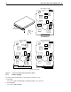
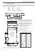
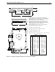
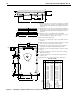
Figure 4. Locations of PCB components listed in Table 3
6.4.2 Relative humidity
The values below assume that no condensation on the drive occurs.
a. Operating
5% to 90% relative humidity with a maximum gradient of 10% per hour.
b. Non-Operating
5% to 95% relative humidity.
Model “N” PCB
HDA Temp.
Check Point
*
J1
Bottom side of PCB
*
U8
U6
U17
U6
U6
U16
U7
U2
U1
U4
U13
U17
U13
U17
U13
U14
U15
U19
U5
U8
U16
U7
U2
U1
U4
U14
U15
U19
U5
Model “W/WD” PCB
*
Model “WC/DC” PCB
PCB 1
PCB 2
PCB 3
*
U8
U16
U7
U2
U1
U4
U14
U15
U19
U5
J1
J1
.5"