
Product manual


26 Barracuda 4LP Product Manual, Rev. D
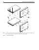
6.5 Mechanical specifications
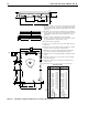
The following nominal dimensions are exclusive of the decorative front panel accessory. However, dimensions
of the front panel are shown in figure below. Refer to Figures 6a, 6b, and 6c for detailed mounting configuration
dimensions. See Section 8.4, “Drive mounting.”
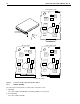
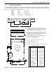
Figure 6a. Mounting configuration dimensions for models “N”
Height: 1.00 in 25.4 mm
Width: 4.00 in 101.6 mm
Depth: 5.74 in 145.8 mm
Weight: 1.5 pounds 0.68 kilograms
A
F
D
E
L
[1]
[3]
B
G
C
[4]
Inches
A
B
C
D
E
F
G
H
J
K
L
M
N
P
R
S
T
U
V
W
145.80
101.60
25.40
60.00
15.75
101.60
6.35
44.45
95.25
60.20
25.4
101.6
4.83
0.381
3.63
6.60
0.76
9.80
57.53
52.71
5.74
4.00
1.00
2.362
.620
4.000
.250
1.750
3.750
2.370
1.00
4.000
0.19
0.015
0.143
0.260
0.030
0.386
2.265
2.075
± .010
± .010
+ .021
– .009
± .010
± .020
± .010
+ .010
– .005
± .010
± .010
± .020
± .010
± .010
± .010
max
± .25
± .25
+ .53
– .22
± .25
± .50
± .25
+ .25
– .12
± .25
± .25
± .50
± .25
± .25
± .25
max
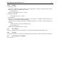
Dimension Table
Millimeters
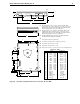
Mounting holes three on each side, 6-32 UNC. Max
screw length into side of drive 0.15 in. (3.81 mm). Screw
tightening torque 6.0 in-lb (.675 NM) max with minimum
thread engagement of 0.12 in. (3.05 mm).
Mounting holes four on bottom, 6-32 UNC. Max screw
length into bottom of drive 0.15 in. (3.81 mm). Screw
tightening torque 6.0 in-lb (.675 NM) max with minimum
thread engagement of 0.12 in. (3.05 mm).
Power and interface connectors can extend past the
"A" dimension by 0.040 in. (1.02 mm).
Decorative front panel (optional).
Centerline of pad for Pin 1 of power connector.
Centerline of pad for Pin 1 of J6.
Centerline of pad for Pin 1 of J2.
Dimensions to Pin 1 of each connector are nominal values.
Notes:
[1]
[2]
[3]
[4]
[5]
[6]
[7]
[8]
J
[5] R
H
S [7]
[7] T
J2
J6 LED
K
W [6]
[2]
M
V
N
[4]
U [6]
P
[8]
[8]