
Product manual


68 Barracuda 4LP Product Manual, Rev. D
9.7 Electrical description
“N” and “W” models use single-ended interface signals. These signals must be terminated with 110-ohm active
termination circuits at each end of the total cable. Single-ended circuits use open collector or three state driv-
ers. All of these models can be configured to provide the SCSI termination.
“WD” models use differential interface signals and each of these must be terminated at each end of the total
cable with 330 ohms to +5V and 330 ohms to ground with 150 ohms between each differential pair. All I/O cir-
cuits are open collector, three state drivers. Differential I/O drives are shipped without terminators. These
drives have no provisions for adding terminator sockets on the PCB. This means some method of external ter-
mination must be provided by the user when termination is required.
“WC” and “DC” models use the single connection attachment (SCA) connector. This 80-pin connector is
designed to plug directly into a back panel or plane. No external cables are required. Active terminators on the
back panel must be provided by the user. This connector is not recommended where cabling is required.
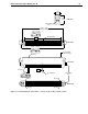
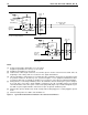
9.7.1 Single-ended drivers/receivers
For “N,” “W,” and “WC” models which use single-ended drivers and receivers, typical circuits are shown in Fig-
ure 12. Terminator circuits (Note [1]) are to be enabled only when the disc drive is first or last in the daisy-chain.
Transmitter characteristics
Single-ended drives use an ANSI SCSI compatible open collector single-ended driver. This driver is capable of
sinking a current of 48 mA with a low level output voltage of 0.4 volt.
Receiver characteristics
Single-ended drives use an ANSI SCSI single-ended receiver with hysteresis gate or equivalent as a line
receiver.
Figure 12. Single-ended transmitters and receivers
Notes.
[1] Part of active terminator circuits. Non-removable LSI terminators, enabled in the drive (models “N” and
“W” only) with jumper plug TE when it is first or last in the daisy-chain.
[2] ANSI SCSI compatible circuits.
[3] Total interface cable length should not exceed that specified in Section 9.6.3.1.
[4] Interface signal levels and logical sense at the drive I/O connector for “N,” “W,” and “WC” models are
defined as follows:
Vil (low-level input voltage) = 1.0 V maximum (signal true); minimum = Vss – 0.5 V.
Vih (high-level input voltage) = 1.9 V minimum (signal false); maximum = Vdd +0.5V.
Vihys (Input Hysteresis) = 425 mV minimum
Transmitter
(or transceiver)
Line Driver
Flat
Cable
Pair
[3]
[5]
[2]
[4]
[1]
110
Ohm
[4]
[1]
110
Ohm
Receiver
Line Receiver
[2]
TP TP