Product Manual Barracuda 7200.8 PATA ST3400832A ST3400632A ST3300831A ST3300631A ST3250823A ST3250623A ST3200826A 100323825 Rev.
©2006-2007, Seagate Technology LLC All rights reserved. Publication number: 100323825, Rev. F August 2007 Seagate, Seagate Technology and the Wave logo are registered trademarks of Seagate Technology LLC in the United States and/or other countries. Barracuda, SeaTools and SeaTDD are either trademarks or registered trademarks of Seagate Technology LLC or one of its affiliated companies in the United States and/or other countries.
Contents 1.0 Introduction. . . . . . . . . . . . . . . . . . . . . . . . . . . . . . . . . . . . . . . . . . . . . . . . . . . . . . . . . . . . . . . . . . . 1 2.0 Drive specifications . . . . . . . . . . . . . . . . . . . . . . . . . . . . . . . . . . . . . . . . . . . . . . . . . . . . . . . . . . . . 3 2.1 Specification summary table . . . . . . . . . . . . . . . . . . . . . . . . . . . . . . . . . . . . . . . . . . . . . . . . 3 2.2 Formatted capacity . . . . . . . . . . . . . . . . . . . . . . . .
ii Barracuda 7200.8 PATA Product Manual, Rev.
List of Figures Figure 1. Figure 2. Figure 3. Figure 4. Figure 5. Figure 6. Figure 7. Typical 5V startup and operation current profile . . . . . . . . . . . . . . . . . . . . . . . . . . . . . . . . . . . Typical 12V startup and operation current profile . . . . . . . . . . . . . . . . . . . . . . . . . . . . . . . . . . Breather filter hole location . . . . . . . . . . . . . . . . . . . . . . . . . . . . . . . . . . . . . . . . . . . . . . . . . . . Master/slave jumper settings . . . . . . . . . . . . . .
iv Barracuda 7200.8 PATA Product Manual, Rev.
1.0 Introduction This manual describes the functional, mechanical and interface specifications for the following Seagate® Barracuda® 7200.8 PATA model drives: Barracuda 7200.8 PATA • ST3400832A • ST3400632A • ST3300831A • ST3300631A • ST3250823A • ST3250623A • ST3200826A These drives provide the following key features: • 7,200-RPM spindle speed • 8-Mbyte buffer on: ST3400832A, ST3300831A, ST3250823A and ST3200826A.
2 Barracuda 7200.8 PATA Product Manual, Rev.
2.0 Drive specifications Unless otherwise noted, all specifications are measured under ambient conditions, at 25°C, and nominal power. For convenience, the phrases the drive and this drive are used throughout this manual to indicate ST3400832A, ST3400632A, ST3300831A, ST3300631A, ST3250823A, ST3250623A, and ST3200826A model drives. 2.1 Specification summary table The specifications listed in tables 1, 2, and 3 are for quick reference.
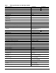
Table 1: Drive specifications for 400 Gbyte models Drive specification 4 ST3400832A ST3400632A Formatted Gbytes (512 bytes/sector)* 400 400 Guaranteed sectors 781,422,768 781,422,768 Bytes per sector 512 Default sectors per track 63 Default read/write heads 16 Default cylinders 16,383 Recording density, BPI (bits/in max) 763,000 Track density, TPI (tracks/in avg.
Drive specification ST3400832A ST3400632A Altitude, nonoperating (below mean sea level, max) –60.96 m to 12,192 m (–200 ft. to 40,000+ ft.) Operational Shock (Gs max at 2 msec) 63 Non-Operational Shock (Gs max at 2 msec) 300 Gs Vibration, operating 5–22 Hz: Limited displacement 23–350 Hz: 0.5 G acceleration Vibration, nonoperating 5–22 Hz: Limited displacement 23–350 Hz: 5.0 Gs Drive acoustics, sound power (bels) Idle** 2.8 (typical) 3.4 (max) Performance seek 3.7 (typical) 3.
Table 2: Drive specifications for 300 Gbyte models Drive specification 6 ST3300831A ST3300631A Formatted Gbytes (512 bytes/sector)* 300 300 Guaranteed sectors 586,072,368 586,072,368 Bytes per sector 512 Default sectors per track 63 Default read/write heads 16 Default cylinders 16,383 Recording density, BPI (bits/in max) 763,000 Track density, TPI (tracks/in avg.
Drive specification ST3300831A ST3300631A Altitude, nonoperating (below mean sea level, max) –60.96 m to 12,192 m (–200 ft. to 40,000+ ft.) Operational Shock (Gs max at 2 msec) 63 Non-Operational Shock (Gs max at 2 msec) 300 Gs Vibration, operating 5–22 Hz: Limited displacement 23–350 Hz: 0.5 G acceleration Vibration, nonoperating 5–22 Hz: Limited displacement 23–350 Hz: 5.0 Gs Drive acoustics, sound power (bels) Idle** 2.8 (typical) 3.4 (max) Performance seek 3.7 (typical) 3.
Table 3: Drive specifications for 250 and 200 Gbyte models Drive specification 8 ST3250823A ST3250623A ST3200826A Formatted Gbytes (512 bytes/sector)* 250 250 200 Guaranteed sectors 488,397,168 488,397,168 390,721,968 Bytes per sector 512 Default sectors per track 63 Default read/write heads 16 Default cylinders 16,383 Recording density, BPI (bits/in max) 763,000 Track density, TPI (tracks/in avg.
Drive specification ST3250823A Altitude, operating –60.96 m to 3,048 m (–200 ft. to 10,000+ ft.) Altitude, nonoperating (below mean sea level, max) –60.96 m to 12,192 m (–200 ft. to 40,000+ ft.) Operational Shock (Gs max at 2 msec) 63 ST3250623A Non-Operational Shock (Gs max at 2 msec) 300 Gs Vibration, operating 5–22 Hz: Limited displacement 23–350 Hz: 0.5 G acceleration Vibration, nonoperating 5–22 Hz: Limited displacement 23–350 Hz: 5.
2.2 Formatted capacity Model Formatted capacity Guaranteed sectors Bytes per sector ST3400832A 400 Gbytes 781,422,768 512 ST3400632A 400 Gbytes 781,422,768 512 ST3300831A 300 Gbytes 586,072,368 512 ST3300631A 300 Gbytes 586,072,368 512 ST3250823A 250 Gbytes 488,397,168 512 ST3250623A 250 Gbytes 488,397,168 512 ST3200826A 200 Gbytes 390,721,968 512 2.2.
2.5 Physical characteristics Drive specification Maximum height (mm) (inches) 26.11 1.028 (mm) (inches) 101.85 4.010 (mm) (inches) 146.99 5.787 (grams) (pounds) 635 1.39 Maximum width Maximum length Max weight 2.6 Seek time Seek measurements are taken with nominal power at 25°C ambient temperature. All times are measured using drive diagnostics.
2.8 Power specifications The drive receives DC power (+5V or +12V) through a four-pin standard drive power connector. 2.8.1 Power consumption Power requirements for the drives are listed in the table on page 12. Typical power measurements are based on an average of drives tested, under nominal conditions, using +5.0V and +12.0V input voltage at 25°C ambient temperature. • Spinup power Spinup power is measured from the time of power-on to the time that the drive spindle reaches operating speed.
2.8.1.1 Typical current profile Figure 1 Typical 5V startup and operation current profile Figure 2 Typical 12V startup and operation current profile 2.8.2 Conducted noise Input noise ripple is measured at the host system power supply across an equivalent 80-ohm resistive load on the +12 volt line or an equivalent 15-ohm resistive load on the +5 volt line. • Using 12-volt power, the drive is expected to operate with a maximum of 120 mV peak-to-peak square-wave injected noise at up to 10 MHz.
2.8.4 Power-management modes The drive provides programmable power management to provide greater energy efficiency. In most systems, you can control power management through the system setup program.
2.9 Environmental specifications 2.9.1 Ambient temperature Ambient temperature is defined as the temperature of the environment immediately surrounding the drive. Actual drive case temperature should not exceed 69°C (156°F) within the operating ambient conditions for standard models, or 64°C (147°F) within the operating ambient conditions for all models. Recommended measurement locations are shown in See Figure 6 on page 25.
2.9.5 Shock All shock specifications assume that the drive is mounted securely with the input shock applied at the drive mounting screws. Shock may be applied in the X, Y or Z axis. 2.9.5.1 Operating shock These drives comply with the performance levels specified in this document when subjected to a maximum operating shock of 63 Gs based on half-sine shock pulses of 2 msec. Shocks should not be repeated more than two times per second. 2.9.5.
2.10 Acoustics Drive acoustics are measured as overall A-weighted acoustic sound power levels (no pure tones). All measurements are consistent with ISO document 7779. Sound power measurements are taken under essentially free-field conditions over a reflecting plane. For all tests, the drive is oriented with the cover facing upward. Note. For seek mode tests, the drive is placed in seek mode only. The number of seeks per second is defined by the following equation: (Number of seeks per second = 0.
2.12 Reliability Nonrecoverable read errors 1 per 1014 bits read, max. Annualized Failure Rate (AFR) 0.34% (nominal power, 25°C ambient temperature) Contact start-stop cycles 50,000 cycles (at nominal voltage and temperature, with 60 cycles per hour and a 50% duty cycle) Service Life 5 Years Warranty 5 years on distribution units. To determine the warranty for a specific drive, use a web browser to access the following web page: www.seagate.
These drives have been tested and comply with the Electromagnetic Interference/Electromagnetic Susceptibility (EMI/EMS) for Class B products. Drives are tested in a representative, end-user system by a Korean-recognized lab. • EUT name (model numbers): ST3400832A, ST3400632A, ST3360832A, ST3300831A, ST3300631A, ST3250823A, ST3250623A and ST3200826A.
2.14 Environmental protection Seagate designs its products to meet environmental protection requirements worldwide, including regulations restricting certain chemical substances. European Union Restriction of Hazardous Substances (RoHS) The European Union Restriction of Hazardous Substances (RoHS) Directive restricts the presence of chemical substances, including Lead (Pb), in electronic products effective July 2006.
3.0 Configuring and mounting the drive This section contains the specifications and instructions for configuring and mounting the drive. 3.1 Handling and static discharge precautions After unpacking, and before installation, the drive may be exposed to potential handling and electrostatic discharge (ESD) hazards.
3.2 Breather filter hole precautions This section contains information regarding the precautions which should be taken regarding the breather filter hole in Seagate hard disc drives. Proper precautions should be taken to ensure full functionality and prevent possible damage to the drive. Breather hole Do not cover or seal this hole. Figure 3 Breather filter hole location Caution: Do not cover, seal, or insert any object into this hole.
3.3 Jumper settings 3.3.1 Master/slave configuration The options jumper block shown in Figure 4 is used to configure the drive for operation. It is the 8-pin dual header between the interface connector and the power connector. Use the following settings to configure the drive as a master or a slave. Master or single drive. The drive is configured at the factory for a master or single-drive operation with a jumper set on pins 7 and 8. Drive as slave. Remove all jumpers.
3.3.4 Ultra ATA/100 cable An 80-conductor 40-pin cable is required to run Ultra DMA mode 3, mode 4, and mode 5. This cable uses even-numbered conductors connected to the ground pins to improve signal integrity. Master Pin 1 Co Mo mpu the ter rbo ard Slave Figure 5 Note. 3.4 Note. If you are using a 40-pin, 80-conductor cable, attach the blue connector to the motherboard, the black connector to the master drive, and the gray connector to the slave.
Notes: 1. Dimensions are shown in inches (mm). 2 Dimensions per SFF-8301 specification. 0.228 (5.79) 1.028 max (26.11) 2.83 (71.80) 3 x 0.25 0.010 (6.35 0.037) both sides 1.122 0.02 (28.5 0.51) 1.638 (41.61 0.01 0.25) 0.178 (4.27) 2.23 (56.56) 3.71 (94.35) 2 1.625 0.020 (41.28 0.51) 5.787 max (146.99) 1.75 0.01 (44.45 0.25) 4.0 0.01 (101.60 0.25) 4 x 6-32 UNC-2B 0.150 (3.81) max. fastener penetration. 3 threads minimum engagement.
26 Barracuda 7200.8 PATA Product Manual, Rev.
4.0 ATA interface These drives use the industry-standard ATA task file interface that supports 16-bit data transfers. It supports ATA programmed input/output (PIO) modes 0–4; multiword DMA modes 0–2, and Ultra DMA modes 0–5. The drive also supports the use of the IORDY signal to provide reliable high-speed data transfers. You can use a daisy-chain cable to connect two drives to a single AT host bus.
4.1.1 Supported ATA commands The following table lists ATA-standard commands that the drive supports. For a detailed description of the ATA commands, refer to the Draft ATA-7 Standard. See “S.M.A.R.T. commands” on page 33 for details and subcommands used in the S.M.A.R.T. implementation.
Command name Command code (in hex) Security Erase Unit F4H Security Freeze F5H Security Set Password F1H Security Unlock F2H Seek 70H Set Features EFH Set Max Address F9H Note: Individual Set Max Address commands are identified by the value placed in the Set Max Features register as defined to the right. Address: Password: Lock: Unlock: Freeze Lock: Set Max Address Extended 37H Set Multiple Mode C6H Sleep 99H or E6H S.M.A.R.T. Disable Operations B0H / D9H S.M.A.R.T.
4.1.2 Identify Device command The Identify Device command (command code ECH) transfers information about the drive to the host following power up. The data is organized as a single 512-byte block of data, whose contents are shown in the Table 7 on page 28. All reserved bits or words should be set to zero. Parameters listed with an “x” are drive-specific or vary with the state of the drive. See Section 2.0 on page 3 for default parameter settings.
Word Description Value 59 Number of sectors transferred during a Read Multiple or Write Multiple command xxxxH 60–61 Total number of user-addressable LBA sectors available (see Section 2.2 for related information) *Note: The maximum value allowed in this field is: 0FFFFFFFh (268,435,455 sectors, 137 Gbytes). Drives with capacities over 137 Gbytes will have 0FFFFFFFh in this field and the actual number of useraddressable LBAs specified in words 100-103.
Word Description Value 128 Security status 0001H 129–159 Seagate-reserved xxxxH 160–254 ATA-reserved 0000H 255 Integrity word xxA5H Note. Advanced Power Management (APM) and Automatic Acoustic Management (AAM) features are not supported Note. See the bit descriptions below for words 63, 88, and 93 of the Identify Drive data: Description (if bit is set to 1) 32 Bit Word 63 0 Multiword DMA mode 0 is supported. 1 Multiword DMA mode 1 is supported.
4.1.3 Set Features command This command controls the implementation of various features that the drive supports. When the drive receives this command, it sets BSY, checks the contents of the Features register, clears BSY and generates an interrupt. If the value in the register does not represent a feature that the drive supports, the command is aborted. Power-on default has the read look-ahead and write caching features enabled.
This drive is shipped with S.M.A.R.T. features disabled. You must have a recent BIOS or software package that supports S.M.A.R.T. to enable this feature. The table below shows the S.M.A.R.T. command codes that the drive uses. Code in features register S.M.A.R.T. command D0H S.M.A.R.T. Read Data D2H S.M.A.R.T. Enable/Disable Attribute Autosave D3H S.M.A.R.T. Save Attribute Values D4H S.M.A.R.T. Execute Off-line Immediate (runs DST) D5H S.M.A.R.T. Read Log Sector D6H S.M.A.R.T.
5.0 Seagate Technology support services Internet For information regarding Seagate products and services, visit www.seagate.com. Worldwide support is available 24 hours daily by email for your questions. Presales Support: Presales@Seagate.com Technical Support: DiscSupport@Seagate.com Warranty Support: http://www.seagate.com/support/service/index.html mySeagate my.seagate.com is the industry's first Web portal designed specifically for OEMs and distributors.
Customer Service Operations Warranty Service Seagate offers worldwide customer support for Seagate products. Seagate distributors, OEMs and other direct customers should contact their Seagate Customer Service Operations (CSO) representative for warrantyrelated issues. Resellers or end users of drive products should contact their place of purchase or Seagate warranty service for assistance. Have your serial number and model or part number available.
Index A acoustics 17 Active mode 14 agency certification (regulatory) 18 alternate capacity jumper 23 altitude 15 ambient conditions 3 ambient temperature 11, 15 areal density 1, 10 ATA interface 27 ATA-standard commands 28 Australian C-Tick 19 autodetection 1 average seek time 11 B BIOS 23 BPI 10 breather filter hole precautions 22 buffer 10 burst 1 C cable 24 cable select 1 cable-select option 23 cache 1, 10 case temperature 15 CE mark 18 certification 18 Check Power Mode 28 commands 28 compliance 18 co
Identify Device command 30 Idle 12, 28 Idle and Standby timers 14 Idle Immediate 28 Idle mode 14 Idle mode power 12 IEC950 18 Information Technology Equipment 18 Initialize Device Parameters 28 interface 10, 27 interface signals 27 interference 19 interleave 10 internal data-transfer rate OD 10 ISO document 7779 17 J jumper settings 23 K Korean RRL 18 L LBA mode 10 length 11 logical geometry 10 M maintenance 18 master 23 master/slave 1 Master/slave configuration 23 maximum temperature 15 measurement loc
S.M.A.R.T. Enable/Disable Autosave 29 S.M.A.R.T. Execute Offline 29 S.M.A.R.T. Read Attribute Thresholds 29 S.M.A.R.T. Read Data 29 S.M.A.R.T. Read Log Sector 29 S.M.A.R.T. Return Status 29 S.M.A.R.T. Save Attribute Values 29 S.M.A.R.T.
44 Barracuda 7200.8 PATA Product Manual, Rev.
Seagate Technology LLC 920 Disc Drive, Scotts Valley, California 95066-4544, USA Publication Number: 100323825, Rev. F, Printed in U.S.A.