Product Manual Cheetah 15K.6 FC ST3450856FC ST3450056FC (FDE) ST3300656FC ST3300056FC (FDE) ST3146356FC ST3146756FC (FDE) 100465943 Rev.
©2007, 2008, Seagate Technology LLC All rights reserved. Publication number: 100465943, Rev. D August 2008 Seagate, Seagate Technology and the Wave logo are registered trademarks of Seagate Technology LLC in the United States and/or other countries. Cheetah, SeaTools and SeaTDD are either trademarks or registered trademarks of Seagate Technology LLC or one of its affiliated companies in the United States and/ or other countries.
Contents 1.0 Scope . . . . . . . . . . . . . . . . . . . . . . . . . . . . . . . . . . . . . . . . . . . . . . . . . . . . . . . . . . . . . . . . . . . . . . . . 1 2.0 Applicable standards and reference documentation . . . . . . . . . . . . . . . . . . . . . . . . . . . . . . . . . 2.1 Standards . . . . . . . . . . . . . . . . . . . . . . . . . . . . . . . . . . . . . . . . . . . . . . . . . . . . . . . . . . . . . . 2.1.1 Electromagnetic compatibility. . . . . . . . . . . . . . . . . . . . . . . . . .
6.0 Physical/electrical specifications . . . . . . . . . . . . . . . . . . . . . . . . . . . . . . . . . . . . . . . . . . . . . . . . 6.1 AC power requirements . . . . . . . . . . . . . . . . . . . . . . . . . . . . . . . . . . . . . . . . . . . . . . . . . . . 6.2 DC power requirements . . . . . . . . . . . . . . . . . . . . . . . . . . . . . . . . . . . . . . . . . . . . . . . . . . . 6.2.1 Conducted noise immunity . . . . . . . . . . . . . . . . . . . . . . . . . . . . . . . . . . . . . . . . . 6.2.
9.6 10.0 9.5.4 Pin descriptions . . . . . . . . . . . . . . . . . . . . . . . . . . . . . . . . . . . . . . . . . . . . . . . . . 9.5.5 FC-AL transmitters and receivers . . . . . . . . . . . . . . . . . . . . . . . . . . . . . . . . . . . 9.5.6 Power . . . . . . . . . . . . . . . . . . . . . . . . . . . . . . . . . . . . . . . . . . . . . . . . . . . . . . . . . 9.5.7 Fault LED Out . . . . . . . . . . . . . . . . . . . . . . . . . . . . . . . . . . . . . . . . . . . . . . . . . . 9.5.8 Active LED Out. . .
iv Cheetah 15K.6 FC Product Manual, Rev.
1.0 Scope This manual describes Seagate Technology® LLC, Cheetah® 15K.6 FC (Fibre Channel) disc drives. Cheetah 15K.6 FC drives support the Fibre Channel Arbitrated Loop and SCSI Fibre Channel Protocol specifications to the extent described in this manual. The Fibre Channel Interface Manual (part number 100293070) describes the general Fibre Channel Arbitrated Loop characteristics of this and other Seagate Fibre Channel drives.
2 Cheetah 15K.6 FC Product Manual, Rev.
2.0 Applicable standards and reference documentation The drive has been developed as a system peripheral to the highest standards of design and construction. The drive depends upon its host equipment to provide adequate power and environment in order to achieve optimum performance and compliance with applicable industry and governmental regulations. Special attention must be given in the areas of safety, power distribution, shielding, audible noise control, and temperature regulation.
2.1.2 Electromagnetic compliance Seagate uses an independent laboratory to confirm compliance with the directives/standards for CE Marking and C-Tick Marking. The drive was tested in a representative system for typical applications. The selected system represents the most popular characteristics for test platforms.
tory analytical validation testing, and an internal auditing process to ensure that all standard operating procedures are complied with. 2.3 Reference documents ANSI Fibre Channel Documents X3.230-1994 X3.297.1997 X3.303.1998 X3.272-1996 X3.
6 Cheetah 15K.6 FC Product Manual, Rev.
3.0 General description Cheetah 15K.6 FC drives provide high performance, high capacity data storage for a variety of systems including engineering workstations, network servers, mainframes, and supercomputers. Cheetah 15K.6 FC drives support 4-Gbit Fibre Channel. Cheetah 15K.
3.1 Standard features Cheetah 15K.
3.2 Media description The media used on the drive has an aluminum substrate coated with a thin film magnetic material, overcoated with a proprietary protective layer for improved durability and environmental protection. 3.3 • • • • • • • Performance Programmable multi-segmentable cache buffer 400 Mbytes/sec maximum instantaneous data transfers per port 15k RPM spindle; average latency = 2.
3.6 Factory-installed options You may order the following items which are incorporated at the manufacturing facility during production or packaged before shipping. Some of the options available are (not an exhaustive list of possible options): • Other capacities can be ordered depending on sparing scheme and sector size requested. • Single-unit shipping pack. The drive is normally shipped in bulk packaging to provide maximum protection against transit damage.
4.0 Performance characteristics This section provides detailed information concerning performance-related characteristics and features of Cheetah 15K.6 FC drives. 4.1 Internal drive characteristics Drive capacity* Read/write data heads Tracks per inch Peak bits per inch Areal density Internal data rate Disc rotation speed Avg rotational latency ST3450856FC ST3450056FC 450 8 150,000 1,100k 165 1.95 15k 2.0 ST3300656FC ST3300056FC 300 6 150,000 1,100k 165 1.95 15k 2.
4.2.2 Format command execution time (minutes) When changing sector sizes, the format times shown below may need to be increased by 30 minutes. ST3450856FC ST3450056FC ST3300656FC ST3300056FC ST3146356FC ST3146756FC 176 144 100 88 72 50 Maximum (with verify) Maximum (without verify) Note. 4.2.3 There is no significant difference in the format time between FDE and non-FDE models of the same capacity.
4.4 Prefetch/multi-segmented cache control The drive provides a prefetch (read look-ahead) and multi-segmented cache control algorithms that in many cases can enhance system performance. Cache refers to the drive buffer storage space when it is used in cache operations. To select this feature, the host sends the Mode Select command with the proper values in the applicable bytes in page 08h.
are to be written are already stored in the cache from a previous read or write command. If there are, the respective cache segments are cleared. The new data is cached for subsequent Read commands.
5.0 Reliability specifications The following reliability specifications assume correct host and drive operational interface, including all interface timings, power supply voltages, environmental requirements and drive mounting constraints. Seek error rate: Read Error Rates Recovered Data Unrecovered Data Miscorrected Data Interface error rate: Annualized Failure Rate (AFR): Preventive maintenance: 5.
5.1.3 Seek errors A seek error is defined as a failure of the drive to position the heads to the addressed track. After detecting an initial seek error, the drive automatically performs an error recovery process. If the error recovery process fails, a seek positioning error (Error code = 15h or 02h) will be reported with a Hardware error (04h) in the Sense Key. Recoverable seek errors are specified at Less than 10 errors in 108 seeks.
present, loop operation may continue. If the bypass circuit is not present, loop operation will be halted while the self test of the FC interface runs. When the self test completes successfully, the control line to the bypass circuit is disabled and the drive enters the FC-AL Initializing state. The receiver on the next device in the loop must synchronize to output of the newly inserted drive. If the self-test fails, the control line to the bypass circuit remains in the Enable Bypass state. Note.
Determining rate S.M.A.R.T. monitors the rate at which errors occur and signals a predictive failure if the rate of degraded errors increases to an unacceptable level. To determine rate, error events are logged and compared to the number of total operations for a given attribute. The interval defines the number of operations over which to measure the rate. The counter that keeps track of the current number of operations is referred to as the Interval Counter. S.M.A.R.T. measures error rates.
5.2.6 Drive Self Test (DST) Drive Self Test (DST) is a technology designed to recognize drive fault conditions that qualify the drive as a failed unit. DST validates the functionality of the drive at a system level. There are two test coverage options implemented in DST: 1. Extended test 2. Short text The most thorough option is the extended test that performs various tests on the drive and scans every logical block address (LBA) of the drive.
5.2.6.2.3 Short and extended tests DST has two testing options: 1. short 2. extended These testing options are described in the following two subsections. Each test consists of three segments: an electrical test segment, a servo test segment, and a read/verify scan segment. Short test (Function Code: 001b) The purpose of the short test is to provide a time-limited test that tests as much of the drive as possible within 120 seconds.
5.2.
22 Cheetah 15K.6 FC Product Manual, Rev.
6.0 Physical/electrical specifications This section provides information relating to the physical and electrical characteristics of the drive. 6.1 AC power requirements None. 6.2 DC power requirements The voltage and current requirements for a single drive are shown below. Values indicated apply at the drive connector. Notes are shown following table 6. Cheetah 15K.6 FC Product Manual, Rev.
Table 2: ST3450856FC DC power requirements 1 Gbit Notes Voltage 2 Gbit 4 Gbit (Amps) (Amps) (Amps) (Amps) (Amps) (Amps) +5V +12V [2] +5V +12V [2] +5V +12V [2] Regulation [5] ±5% ±5% [2] ±5% ±5% [2] ±5% ±5% [2] Avg idle current DCX [1] [7] 0.49 0.77 0.51 0.77 0.57 0.77 Maximum starting current (peak DC) DC 3σ [3] 0.72 1.89 0.69 1.89 0.81 1.89 (peak AC) AC 3σ [3] 1.02 4.19 0.83 4.23 1.13 4.21 3σ [1] [4] 0.55 0.04 0.58 0.04 0.64 0.04 [1] [6] 0.53 1.
Table 4: ST3300656FC DC power requirements 1 Gbit Notes Voltage 2 Gbit 4 Gbit (Amps) (Amps) (Amps) (Amps) (Amps) (Amps) +5V +12V [2] +5V +12V [2] +5V +12V [2] Regulation [5] ±5% ±5% [2] ±5% ±5% [2] ±5% ±5% [2] Avg idle current DCX [1] [7] 0.51 0.66 0.54 0.66 0.60 0.67 Maximum starting current (peak DC) DC 3σ [3] 0.68 1.76 0.71 1.77 0.95 1.77 (peak AC) AC 3σ [3] 0.94 3.90 0.95 3.94 1.14 4.05 3σ [1] [4] 0.62 0.04 0.64 0.04 0.70 0.04 [1] [6] 0.57 1.
Table 6: ST3146356FC DC power requirements 1 Gbit Notes Voltage 2 Gbit 4 Gbit (Amps) (Amps) (Amps) (Amps) (Amps) (Amps) +5V +12V [2] +5V +12V [2] +5V +12V [2] Regulation [5] ±5% ±5% [2] ±5% ±5% [2] ±5% ±5% [2] Avg idle current DCX [1] [7] 0.53 0.53 0.56 0.53 0.63 0.53 Maximum starting current (peak DC) DC 3σ [3] 0.82 1.75 0.68 1.75 0.74 1.75 (peak AC) AC 3σ [3] 1.11 3.42 0.95 3.81 1.00 3.58 3σ [1] [4] 0.62 0.04 0.64 0.04 0.71 0.04 [1] [6] 0.62 0.
[5] [6] [7] Motor command. See paragraph 6.2.1, "Conducted noise immunity." Specified voltage tolerance includes ripple, noise, and transient response. Operating condition is defined as random 8 block reads at 330 I/Os per second for ST3450856FC/ ST3450056FC and 347 I/Os per second for ST3300656FC/ST3300056FC and ST3146356FC/ ST3146756FC models. Current and power specified at nominal voltages.
Figure 1. Typical ST3450856FC current profiles 28 Cheetah 15K.6 FC Product Manual, Rev.
Figure 2. Typical ST3450056FC current profiles Cheetah 15K.6 FC Product Manual, Rev.
Figure 3. Typical ST3300656FC current profiles 30 Cheetah 15K.6 FC Product Manual, Rev.
Figure 4. Typical ST3300056FC current profiles Cheetah 15K.6 FC Product Manual, Rev.
Figure 5. Typical ST3146356FC current profiles 32 Cheetah 15K.6 FC Product Manual, Rev.
Figure 6. Typical ST3146756FC current profiles Cheetah 15K.6 FC Product Manual, Rev.
6.3 Power dissipation 450GB models Typical power dissipation under idle conditions in 4 Gbit operation is 12.09 watts (41.25 BTUs per hour). To obtain operating power for typical random read operations, refer to the following I/O rate curve (see Figure 7). Locate the typical I/O rate for a drive in your system on the horizontal axis and read the corresponding +5 volt current, +12 volt current, and total watts on the vertical axis. To calculate BTUs per hour, multiply watts by 3.4123. Figure 7.
300GB models Typical power dissipation under idle conditions in 4 Gbit operation is 11.04 watts (37.67 BTUs per hour). To obtain operating power for typical random read operations, refer to the following I/O rate curve (see Figure 7). Locate the typical I/O rate for a drive in your system on the horizontal axis and read the corresponding +5 volt current, +12 volt current, and total watts on the vertical axis. To calculate BTUs per hour, multiply watts by 3.4123. Figure 8.
146GB models Typical power dissipation under idle conditions in 4 Gbit operation is 9.51 watts (32.45 BTUs per hour). To obtain operating power for typical random read operations, refer to the following I/O rate curve (see Figure 7). Locate the typical I/O rate for a drive in your system on the horizontal axis and read the corresponding +5 volt current, +12 volt current, and total watts on the vertical axis. To calculate BTUs per hour, multiply watts by 3.4123. Figure 9.
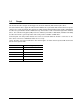
b. Non-operating –40° to 158°F (–40° to 70°C) package ambient with a maximum gradient of 36°F (20°C) per hour. This specification assumes that the drive is packaged in the shipping container designed by Seagate for use with drive. HDA Temp. Check Point 1.0 " .5" Figure 10. Locations of the HDA temperature check point 6.4.2 Relative humidity The values below assume that no condensation on the drive occurs. a. Operating 5% to 95% non-condensing relative humidity with a maximum gradient of 20% per hour.
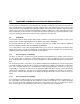
6.4.4 Shock and vibration Shock and vibration limits specified in this document are measured directly on the drive chassis. If the drive is installed in an enclosure to which the stated shock and/or vibration criteria is applied, resonances may occur internally to the enclosure resulting in drive movement in excess of the stated limits. If this situation is apparent, it may be necessary to modify the enclosure to minimize drive movement.
Z X Y Z Y X Figure 11. Recommended mounting Cheetah 15K.6 FC Product Manual, Rev.
6.4.4.2 Vibration a. Operating—normal The drive as installed for normal operation, shall comply with the complete specified performance while subjected to continuous vibration not exceeding 10–500 Hz @ 0.5 G (zero to peak) Vibration may be applied in the X, Y, or Z axis. Operating normal translational random flat profile 10–500 Hz 0.4 g RMS b.
Users should use caution exposing any electronic components to uncontrolled chemical pollutants and corrosive chemicals as electronic drive component reliability can be affected by the installation environment. The silver, copper, nickel and gold films used in Seagate products are especially sensitive to the presence of sulfide, chloride, and nitrate contaminants. Sulfur is found to be the most damaging.
6.5 Mechanical specifications The following nominal dimensions are exclusive of the decorative front panel accessory. However, dimensions of the front panel are shown in figure below. Refer to Figure 12 for detailed mounting configuration dimensions. See Section 8.4, “Drive mounting.” Height (max): Width (max): Depth (max): Weight: 1.028 in 4.010 in 5.787 in ST3450856FC: 1.563 pounds ST3300656FC: 1.53 pounds ST3146356FC: 1.487 pounds 26.11 mm 101.85 mm 146.99 mm 0.709 kilograms 0.694 kilograms 0.
7.0 Defect and error management Seagate continues to use innovative technologies to manage defects and errors. These technologies are designed to increase data integrity, perform drive self-maintenance, and validate proper drive operation. SCSI defect and error management involves drive internal defect/error management and FC system error considerations (errors in communications between the initiator and the drive).
read or re-write attempt. The maximum level used by the drive in LBA recovery is determined by the read and write retry counts. Table 8 equates the read and write retry count with the maximum possible recovery time for read and write recovery of individual LBAs. The times given do not include time taken to perform reallocations. Reallocations are performed when the ARRE bit (for reads) or AWRE bit (for writes) is one, the RC bit is zero, and the recovery time limit for the command has not yet been met.
Table 8: Read and write retry count maximum recovery times [1] Read retry count Maximum recovery time per LBA (cumulative, msec) Write retry count Maximum recovery time per LBA (cumulative, msec) 0 51.87 0 23.94 1 59.85 1 35.91 2 203.49 2 55.86 3 219.45 3 67.83 4 231.42 4 119.79 5 297.38 5 (default) 147.72 6 323.62 7 355.54 8 439.39 9 507.39 10 539.31 11 567.24 12 1,460.86 13 (default) 1,468.74 [1] These values are subject to change.
avoid placing data in suspect locations on the media. Unreadable and recovered error sites will be logged or reallocated per ARRE/AWRE settings. With BMS, the host system can consume less power and system overhead by only checking BMS status and results rather than tying up the bus and consuming power in the process of host-initiated media scanning activity. Since the background scan functions are only done during idle periods, BMS causes a negligible impact to system performance.
8.0 Installation Cheetah 15K.6 FC disc drive installation is a plug-and-play process. There are no jumpers, switches, or terminators on the drive. Simply plug the drive into the host’s 40-pin Fibre Channel backpanel connector (FCSCA)—no cables are required. See Section 9.5 for additional information about this connector. Use the FC-AL interface to select drive ID and all option configurations for devices on the loop.
If forced air is necessary, possible air-flow patterns are shown in Figure 13. The air-flow patterns are created by fans either forcing or drawing air as shown in the illustrations. Conduction, convection, or other forced airflow patterns are acceptable as long as the temperature measurement guidelines of Section 6.4.1 are met. Above unit Note. Air flows in the direction shown (back to front) or in reverse direction (front to back) Under unit Above unit Note.
cally isolating shock mounts. If it is desired for the system chassis to not be connected to the HDA/PCBA ground, the systems integrator or user must provide a nonconductive (electrically isolating) method of mounting the drive in the host equipment. Increased radiated emissions may result if you do not provide the maximum surface area ground connection between system ground and drive ground. This is the system designer’s and integrator’s responsibility. Cheetah 15K.6 FC Product Manual, Rev.
50 Cheetah 15K.6 FC Product Manual, Rev.
9.0 Interface requirements This section partially describes the interface requirements as implemented on Cheetah 15K.6 FC drives. Additional information is provided in the Fibre Channel Interface Manual (part number 100293070). 9.1 FC-AL features This section lists the Fibre Channel-specific features supported by Cheetah 15K.6 FC drives. 9.1.1 Fibre Channel link service frames Table 9 lists the link services supported by Cheetah 15K.6 FC drives.
9.1.2 Fibre Channel task management functions Table 10 lists the Fibre Channel SCSI Fibre Channel Protocol (FC SCSI FCP) task management functions supported. Table 10: Fibre Channel SCSI FCP task management functions Task name Supported Terminate task No Clear ACA Yes Target reset Yes Clear task set Yes Abort task set Yes 9.1.3 Fibre Channel task management responses Table 11 lists the FC SCSI FCP response codes returned for task management functions supported.
9.1.4 Fibre Channel port login Table 12 identifies the required content of the N_Port Login (PLOGI) payload from an initiator.
9.1.5 Fibre Channel port login accept Table 13 identifies the N_Port Login access payload values.
9.1.7 Fibre Channel Process Login Accept Table 15 lists Cheetah 15K.6 FC process login accept payload data. Table 15: Process Login Accept (ACC) payload Bytes 0-15 02 10 00 14 16-31 00 00 00 12 9.1.8 08 00 21 00 00 00 00 00 00 00 00 00 Fibre Channel fabric login Table 16 lists the fabric login payload from the drive.
9.1.9 Fibre Channel fabric accept login Table 17 lists the required content of the Fabric Login Accept (ACC) payload from the fabric.
9.1.10 Fibre Channel Arbitrated Loop options Table 18 lists the FC-AL options supported by Cheetah 15K.6 FC drives. Table 18: FC-AL options supported Option Supported OPEN Half Duplex Accepted from another device. OPEN Full Duplex Sent to open another device. Accepted from another device. Private Loop Yes Public Loop Yes Old Port State No Loop Position Yes Loop Position Report Yes 9.2 Dual port support Cheetah 15K.6 FC drives have two independent FC-AL ports.
Table 19: Supported commands Executable state of standard SCSI commands in the presence of LBA banding (applies to FDE models only) Affected LBA Unlocked ReadLock=Write Lock=False Affected LBA Locked ReadLock=Write Lock=True Executable Executable Command code Supported (Y/N) [4] Command name Affects entire Drive (Y/N) User Data Accessed (Y/N) 00h Y Test unit ready Y N 01h Y Rezero unit Y N Executable Executable 03h Y Request sense Y N Executable Executable Y Extended sense Y
Table 19: Supported commands (continued) Executable state of standard SCSI commands in the presence of LBA banding (applies to FDE models only) Command code Supported (Y/N) [4] Command name Y Power control page (1Ah) Y Information exceptions control page (1Ch) Y Background Scan mode subpage (01h) Affects entire Drive (Y/N) User Data Accessed (Y/N) Affected LBA Unlocked ReadLock=Write Lock=False Affected LBA Locked ReadLock=Write Lock=True 1Bh Y Start unit/stop unit Y Y Executable Execut
Table 19: Supported commands (continued) Executable state of standard SCSI commands in the presence of LBA banding (applies to FDE models only) Command code Supported (Y/N) [4] Command name 3Ah N Copy and verify 3Bh Y Write buffer Affects entire Drive (Y/N) User Data Accessed (Y/N) Affected LBA Unlocked ReadLock=Write Lock=False Affected LBA Locked ReadLock=Write Lock=True N Y Check Condition Check Condition (all modes except modes 4h - 7h, 0Eh, and 0Fh) Y N Executable Executable (mod
Table 19: Supported commands (continued) Executable state of standard SCSI commands in the presence of LBA banding (applies to FDE models only) Command code Supported (Y/N) [4] Command name Y Background Medium Scan page (15h) Y Cache Statistics Counter page (37h) Y Factory Log page (3Eh) 4E-4Fh N Not used 50h N XD write 51h N XP write 52h N XD read 53-54h N Not used Affects entire Drive (Y/N) User Data Accessed (Y/N) Affected LBA Unlocked ReadLock=Write Lock=False Affected LBA L
[3] [4] Reference Mode Sense command 1Ah for mode pages supported. Y = Yes. Command is supported. N = No. Command is not supported. A = Support is available on special request. 9.3.1 Inquiry data Table 20 lists the Inquiry command data that the drive should return to the initiator per the format given in the Fibre Channel Interface Manual. Table 20: Bytes Cheetah 15K.
When power is applied to the drive, it takes saved values from the media and stores them as current values in volatile memory. It is not possible to change the current values (or the saved values) with a Mode Select command before the drive achieves operating speed and is “ready.” An attempt to do so results in a “Check Condition” status. On drives requiring unique saved values, the required unique saved values are stored into the saved values storage location on the media prior to shipping the drive.
Table 21: Mode Sense data saved, default and changeable values for ST3450856FC/ST3450056FC drives MODE DATA HEADER: 00 be 00 10 00 00 00 08 MODE PAGES: DEF CHG 81 0a c0 0b ff 00 00 00 05 00 ff ff 81 0a ff ff 00 00 00 00 ff 00 ff ff DEF CHG 82 0e 80 80 00 00 00 00 00 00 01 3a 00 00 00 00 82 0e ff ff 00 00 00 00 00 00 ff ff 00 00 00 00 DEF CHG 83 16 bb d0 00 00 00 00 03 80 04 c4 02 00 00 01 01 09 00 5f 40 00 00 00 83 16 00 00 00 00 00 00 00 00 00 00 00 00 00 00 00 00 00 00 00 00 00 00 DEF CHG 84 16 0
Table 22: Mode Sense data default and changeable values for ST3300656FC/ST3300056FC drives MODE DATA HEADER: 00 be 00 10 00 00 00 08 MODE PAGES: DEF CHG 81 0a c0 0b ff 00 00 00 05 00 ff ff 81 0a ff ff 00 00 00 00 ff 00 ff ff DEF CHG 82 0e 80 80 00 00 00 00 00 00 01 3a 00 00 00 00 82 0e ff ff 00 00 00 00 00 00 ff ff 00 00 00 00 DEF CHG 83 16 bb d0 00 00 00 00 03 80 04 c4 02 00 00 01 01 09 00 5f 40 00 00 00 83 16 00 00 00 00 00 00 00 00 00 00 00 00 00 00 00 00 00 00 00 00 00 00 DEF CHG 84 16 02 57 08
Table 23: Mode Sense data default and changeable values for ST3146356FC/ST3146756FC drives MODE DATA HEADER: 00 be 00 10 00 00 00 08 MODE PAGES: DEF CHG 81 0a c0 0b ff 00 00 00 05 00 ff ff 81 0a ff ff 00 00 00 00 ff 00 ff ff DEF CHG 82 0e 80 80 00 00 00 00 00 00 01 3a 00 00 00 00 82 0e ff ff 00 00 00 00 00 00 ff ff 00 00 00 00 DEF CHG 83 16 bb d0 00 00 00 00 03 80 04 c4 02 00 00 01 01 09 00 5f 40 00 00 00 83 16 00 00 00 00 00 00 00 00 00 00 00 00 00 00 00 00 00 00 00 00 00 00 DEF CHG 84 16 02 57 08
9.4 Miscellaneous operating features and conditions Table 24 lists various features and conditions. A “Y” in the support column indicates the feature or condition is supported. An “N” in the support column indicates the feature or condition is not supported.
9.5 FC-AL physical interface Figure 14 shows the location of the J1 Fibre Channel single connection attachment (FC-SCA). Figure 16 provides the dimensions of the FC-SCA connector. Details of the physical, electrical, and logical characteristics are provided within this section. The operational aspects of Seagate’s Fibre Channel drives are provided in the Fibre Channel Interface Manual.. J1 interface connector Figure 14. Physical interface 9.5.
9.5.2 Connector requirements Table 26: Recommended mating SCA part numbers Part description Positions Part number Features AMP Vertical (SCA sequence) 40 787317-1 With polarization Berg 40 71781 With polarization Methode 40 512-220-91-101N With polarization Molex 40 717431040 With polarization The FC-AL SCA device connector is illustrated in Figure 16. 1.618 ± .003 in (41.1 ± 0.08 mm) Pin 20 Pin 40 Pin 1 Pin 21 .64 in (16.24 mm) 0.197 ± .003 in 2 places (5.00 ± .08 mm) 1.
Table 27: FC-SCA pin descriptions Pin Signal name Signal type Pin Signal name 1* -EN bypass port A Low Voltage TTL output 21 12 Volts charge 2* 12 Volts 22 Ground 3* 12 Volts 23 Ground 4* 12 Volts 24* +Port A_in 5* -Parallel ESI 25* -Port A_in 6* Ground[1] 26 Ground 7* Active LED out 27* +Port B_in 8* Reserved 28* -Port B_in 9* [2] TTL input 29 Ground [2] Start_1 Open collector out Signal type FC Diff. input pair FC Diff.
9.5.6 Power Power is supplied through the FC-SCA with support for +5 volts and +12 volts. All of the voltage pins in the drive connector are the same length. Four 12 volt pins provide +12 volt power to the drive. The current return for the +12 volt power supply is through the common ground pins. The supply current and return current must be distributed as evenly as possible among the pins. The maximum current typically occurs while the drive motor is starting.
9.5.8 Active LED Out The Active LED Out signal is driven by the drive as indicated in Table 28.
9.5.11 SEL_6 through SEL_0 ID lines The SEL_6 through SEL_0 ID lines determine drive address, and, optionally, for an Enclosure Services Interface. When the Parallel ESI line is high, the enclosure backpanel must provide address information on the SEL line. Refer to table 30 for a mapping of SEL to FC-AL physical addresses (AL_PA). You can think of the SEL lines as the equivalent of a backpanel logic plug. The drives does not provide pull up resistors on these lines.
Table 30: Arbitrated loop physical address (AL_PA) values AL_PA (hex) SEL ID (hex) Setting (dec) AL_PA (hex) SEL ID (hex) Setting (dec) AL_PA (hex) SEL ID (hex) Setting (dec) EF E8 00 01 00 01 A3 9F 2B 2C 43 44 4D 4C 56 57 86 87 E4 E2 02 03 02 03 9E 9D 2D 2E 45 46 4B 4A 58 59 88 89 E1 E0 04 05 04 05 9B 98 2F 30 47 48 49 47 5A 5B 90 91 DC DA 06 07 06 07 97 90 31 32 49 50 46 45 5C 5D 92 93 D9 D6 08 09 08 09 8F 88 33 34 51 52 43 3c 5E 5F 94 95 D5 D4 0A 0
9.5.12 Device control codes The drive inputs a Device Control Code on the DEV_CTRL_CODE lines at power up to determine the link rate on the Fibre Channel ports. Both ports run at the same rate. If the backpanel does not connect to these lines, the drive has 10K ohm pull up resistors that default the device control code to 7 (1.0625 GHz). Table lists the supported codes. Table 31: Device control code values 2 (pin 17) 1 (pin 18) 0 (pin 39) Definition 0 0 0 Reserved for power failure warning.
9.6.2 LED driver signals Fault and Active LED signals are located in the FC-SCA connector (J1). See Table 33 for the output characteristics of the LED drive signals. Table 33: LED drive signal State Current drive available LED off, high 0 < IOH < 100µA LED on, low IOL < -30 mA 9.6.3 Output voltage 0 < VOL < 0.8V FC Differential output The serial output signal voltage characteristics are provided in Table 34.
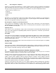
Figure 19 provides the data valid eye diagram for typical and minimum requirements to recover data at the specified interface error rate. The inputs are AC coupled on the drive. Vin (mv) 941 ps 659 ps Typical 376 ps Minimum Figure 19. Receive eye diagram Table 36: Eye diagram data values Link rate 1 GHz 2 GHz 4 GHz Bit time 941 ps 470 ps 235 ps XMIT eye 725 ps min. 315 ps min. 1581/1132 Typical 659 ps 305 ps 145 ps Minimum 395 ps 226 ps 113 ps RCV eye 1. 2. Short Ideal load.
78 Cheetah 15K.6 FC Product Manual, Rev.
10.0 Seagate Technology support services Internet For information regarding Seagate products and services, visit www.seagate.com. Worldwide support is available 24 hours daily by email for your questions. Presales Support: Presales@Seagate.com Technical Support: DiscSupport@Seagate.com Warranty Support: http://www.seagate.com/support/service/index.html mySeagate my.seagate.com is the industry's first Web portal designed specifically for OEMs and distributors.
Customer Service Operations Warranty Service Seagate offers worldwide customer support for Seagate products. Seagate distributors, OEMs and other direct customers should contact their Seagate Customer Service Operations (CSO) representative for warrantyrelated issues. Resellers or end users of drive products should contact their place of purchase or Seagate warranty service for assistance. Have your serial number and model or part number available.
Index Numerics 12 volt pins 71 3rd party reserve command 61 5 volt pins 71 A Abort Sequence (ABTS) 51 abort task set function 52 AC coupling 70 AC power requirements 23 ACA active status 67 ACA active, faulted initiator status 67 Accept (ACC) 51 acoustics 40 active LED Out signal 72 Actual retry count bytes command 58 actuator assembly design 7 adaptive caching 67 Address Discovery (ADISC) 51 addresses 68 AFR 15 air cleanliness 40 air flow 48 illustrated 48 Alternate credit model 53, 56 altitude 37 ambient
D DAR 46 data heads read/write 11 data rate internal 11 data transfer rate 12 data valid eye 77 Date code page command 58 DC power 69 requirements 23 decryption 8 defect and error management 43 defects 43 Deferred Auto-Reallocation 46 deferred error handling 67 description 7 DEV_CTRL_CODE 75 Device Behavior page command 58 device control code values 75 Device Identification page command 58 device selection IDs 47 devices 47 dimensions 42 Disable page out command 59 disc rotation speed 11 Disconnect/reconnec
firmware 8 corruption 61 Firmware download option command 60 Firmware numbers page command 58 flawed sector reallocation 8 FLOGI received on Port A 55 received on Port B 55 Force unit access command 59 form factor 8 format 47 Format command execution time 12 Format page (03h) command 58 Format unit command 58 front panel 42 FS 53, 54, 56 Full Disc Encryption (FDE) Reference Manual 1 function complete, code 00 52 not supported, code 05 52 reject, code 04 52 G Good status 67 gradient 37 ground shift noise 70
Automatic contingent allegiance 67 Deferred error handling 67 FC-AL selective reset 67 Parameter rounding 67 Queue tagging 67 Reporting actual retry count 67 Segmented caching 67 SMP = 1 in Mode Select command 67 Synchronized (locked) spindle operation 67 Zero latency read 67 miscellaneous status support ACA active 67 ACA active, faulted initiator 67 Busy 67 Check condition 67 Condition met/good 67 Good 67 Intermediate/condition met/good 67 Intermediate/good 67 Reservation conflict 67 Task set full 67 misco
requirements, AC 23 requirements, DC 23 sequencing 27 Power control page (1Ah) command 59 power distribution 3 power failure warning 75 Prefetch command 59 prefetch/multi-segmented cache control 13 preventive maintenance 15 private loop FC-AL options 57 Proc Assc 53 Process Accept (ACC) 55 Process Login (PRLI) 51, 54 Process Login Accept (ACC) payload 55 process login payload data 54 Process Logout (PRLO) 51 programmable drive capacity 9 public loop FC-AL options 57 pull down resistor 72 Register FC-4 Type
shock 37, 38 and vibration 37 shock mount 49 signal characteristics 75 LED driver 76 single-unit shipping pack kit 10 SMART 9, 17 SMP = 1 in Mode Select command 67 SO 53, 56 spindle brake 8 Stacked connection req.
Seagate Technology LLC 920 Disc Drive, Scotts Valley, California 95066-4544, USA Publication Number: 100465943, Rev.