EN and ENCSeries Hardware User Manual ENC 2bays NVR ENC16 4bay NVR 16 Channel 2U case NVR
Table of Contents 1 2 3 System Capability ...................................................................................................................................7 1.1 EN and ENC Capabilities (NVR units) ......................................................................................7 1.2 EH-RTHD Capabilities (Hybrid units) ........................................................................................7 Features and Specifications ...........................................
EN Series Connection ...........................................................................................................................24 6 FAQ ......................................................................................................................................................25 7 Appendix A HDD Capacity Calculation ...........................................................................................30 8 Appendix B Compatible SATA HDD.....................................
Welcome Thank you for purchasing our network video recorder! This quick start guide is designed to be a reference tool for your system. Please open the accessory bag to check the items one by one in accordance with the list below. Contact your local retailer if something is missing or damaged in the bag.
Important Safeguards and Warnings 1.Electrical safety All installation and operation here should conform to your local electrical safety codes. We assume no liability or responsibility for all the fires or electrical shock caused by improper handling or installation. 2.Transportation security Heavy stress, violent vibration or water splash are not allowed during transportation, storage and installation. 3.Installation Keep upwards. Handle with care.
Be installed in well ventilated place; do not block the vent.
1 System Capability 1.1 EN and ENC Capabilities (NVR units) The maximum system capability that this product series supports is the following 4-IP 1080P with transmission rate 6mbps every channel @ 30 fps 8-IP 1080P with transmission rate 2mbps every channel @ 12 fps 16-IP 1080P with transmission rate 1.
2 Features and Specifications 2.1 Overview It is a high performance network video recorder. This series product support local preview, multiple-window display, recorded file local storage, remote control and mouse shortcut menu operation, and remote management and control function. All these functions support this series product to be used in various situations. This series product supports centre storage, front-end storage and client-end storage.
Support network backup, USB record backup function, the recorded files can be saved in network storage server, peripheral USB device, burner and etc. Supervise NVR configuration and control power via Ethernet. Support management via WEB. Support peripheral equipment management such as protocol setup and port connection. Support transparent data transmission through RS232/RS485. Support switch between NTSC and PAL.
Relay output. Relay (DC 30V 1A,AC 125V 0.5A(Activation output)) Including one controllable DC +12V output. Storage RS232 Port 2 built-in SATA port s 8 built-in SATA ports N/A 1 peripheral eSATA port One RS232 port to debug transparent COM data. One RS485 port to control PTZ. Support various protocols. RS485 port USB Port 2 peripheral USB ports. 4 peripheral USB port. Network One RJ45 10/100M/1000M self-adaptive Ethernet port. Connection One power port, power adapter.
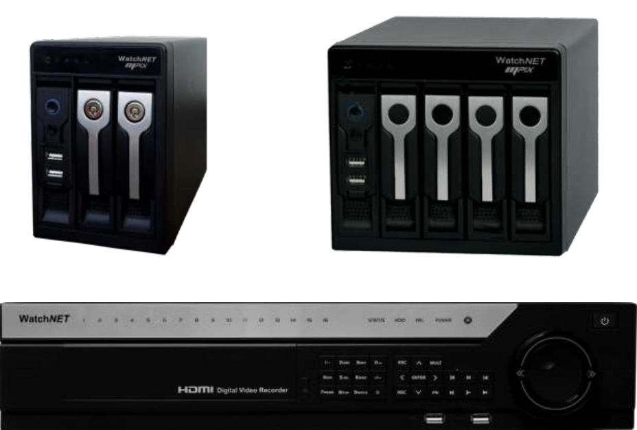
3 Front Panel and Rear Panel 3.1 Front Panel 3.1.1 ENC 2bay series The -1U series NVR front panel is shown as below. See Figure 3-1. Figure 3-1 Please refer to the following sheet for detail information Figure 3-3. 3.1.2 ENC 4bay Series The -1U series NVR front panel is shown as below. See Figure 3-1. Figure 3-2 Please refer to the following sheet for detail information Figure 3-3.
Name Icon Function Power button, press this button for three seconds to boot up or shut Power button down NVR. One-window monitor mode, click this button to display assistant function: PTZ control and image color. Backspace function: in numeral control or text control, press it for 1.5seconds to delete the previous character before the cursor. Assistant Fn In motion detection setup, working with Fn and direction keys to realize setup.
3.1.3 EN Series The EN series front panel is shown as in Figure 3-4. Figure 3-4 Please refer to the following sheet for detail information. Name Icon Function Power button, press this button for three seconds to boot up or shut Power button Number button Input number more than 10 down NVR. Input Arabic number 0-9 Switch channel If you want to input a number more than 10, please click this button -/-- and then input.
In text mode, click it to switch between numeral, English character(small/capitalized) and etc. In HDD management interface, you can click it to switch HDD record information and other information (Menu prompt) Realize other special functions. Fast play Slow play Various fast speeds and normal playback. Multiple slow play speeds or normal playback.
3.2 Rear Panel 3.2.1 ENC 2bay Series The ENC 2bay seriesreal panel is shown as in Figure 3-5. Figure 3-5 3.2.2 ENC 4bay Series The ENC 4bay series is shown as in Figure 3-6. Figure 3-6 Please refer to the following sheet for detailed information.
Port Name Connection Function USB port. Connect to USB mouse. Network port 10M/100M self-adaptive Ethernet port. Connect to the network cable. eSATA eSATA port The external SATA port. It can be connected to the peripheral devices of SATA port. RS232 232 debug COM. HDMI High Definition Multimedia Interface HDMI VGA VGA video output port VGA RS232 It is for general COM debug to configure IP address or transfer transparent COM data. High definition video signal output port.
3.2.3 EN Series The 2U series rear panel is shown as below. See Figure 3-7. Figure 3-7 Please refer to the following sheet for detailed information. Port Name Connection Function Power button Power on/off button. Power input port Input AC 120-220 MIC OUT Audio output port RCA Audio output port. Output analog audio signal to the devices such as sound box. MIC IN Audio input port RCA Bidirectional talk input port. Receive the analog signal from the devices such as speaker or pickup.
Port Name Connection Function control devices such as speed dome PTZ. CTRL 12V Controllable 12V power output. It is to control the on-off relay output. You can use it to enable device alarm function. It can also be used as the power input for some alarm devices such as the smoke detector. +12V eSATA +12V power output port. It is to provide the power to the peripheral devices such as camera or alarm device. The connected device current shall be less than 1A.
Listening Operation At the device end, speak via the speaker or the pickup, and then you can get the audio from the earphone or sound box at the pc-end. 3.3.2 PC-end to the device-end Device Connection Connect the speaker or the pickup to the audio output port in the PC and then connect the earphone or the sound box to the first audio input port in the device rear panel. Login the Web and then enable the corresponding channel real-time monitor.
3.5 Remote Control (Dependent on the unit ) The remote control interface is shown as in Figure 3.9. Please note remote control is not our standard accessory and it is not included in the accessory bag. Figure 3-9 Please refer to the following sheet for detailed information. Serial Number Name Function 1 Power button Click it to boot up or shut down the device. 2 Address Click it to input device number, so that you can control it. 3 Forward Various forward speeds and normal speed playback.
8 normal playback. In reverse playback click this button to pause playback. Cancel 9 10 Go back to previous menu or cancel current operation (close upper interface or control) Record Start or stop record manually In record interface, working with the direction buttons to select the record channel. Click this button for at least 1.5 seconds, system can go to the Manual Record interface. 11 Direction keys Switch current activated control, go to left or right.
4 HDD Installation For the first time install, please be aware that whether the HDDs have been installed. Strongly recommended to use the HDDs which we suggest you to use (high speed HDD that above 7200 rounds), we do not suggest you to use PC specified HDD. 4.1 ENC Series Pleas follow the steps listed below to install the HDD. ① Remove the drive bay ②Fix the four screws on the ③Place the Drive bay back 4.2 EN Series ① Unscrew the screws on the rear panel and cover the upper cover.
④ After wires are connected, place the upper cover on the device and twist the screws on the rear panel.
5 Network Connection ENC Series Connection EN Series Connection Cameras connected to the External POE switch has to be set with a computer.
6 FAQ 1. Device can not boot up properly. There are following possibilities: Input power is not correct. Power connection is not correct. Power switch button is damaged. Program upgrade is wrong. HDD malfunction or something wrong with HDD ribbon. Seagate DB35.1,DB35.2,SV35 or Maxtor 17-g has compatibility problem. Please upgrade to the latest version to solve this problem. Front panel error. Main board is damaged. 2. Device often automatically shuts down or stops running.
6. Can not search local records. There are following possibilities: HDD ribbon is damaged. HDD is broken. Upgraded program is not compatible. The recorded file has been overwritten. Record function has been disabled. 7. Video is distorted when searching local records. There are following possibilities: Video quality setup is too low. Program read error, bit data is too small. There is mosaic in the full screen. Please restart the device to solve this problem.
When there are several decoders, please add 120 Ohm between the PTZ decoder A/B cables furthest end to delete the reverberation or impedance matching. Otherwise the PTZ control is not stable. The distance is too far. 12. Motion detection function does not work. There are following possibilities: Period setup is not correct. Motion detection zone setup is not correct. Sensitivity is too low. For some versions, there is hardware limit. 13. Can not log in client-end or web.
Data amount exceeds backup device capacity. It may result in burner error. Backup device is not compatible. Backup device is damaged. 17. Keyboard can not control device. There are following possibilities: Device serial port setup is not correct Address is not correct When there are several switchers, power supply is not enough. Transmission distance is too far. 18. Alarm signal can not been disarmed. There are following possibilities: Alarm setup is not correct.
No DivX503Bundle.exe or ffdshow-2004 1012 .exe in Windows XP OS. 23. I forgot local menu operation password or network password Please contact your local service engineer or our sales engineer for help. We can guide you to solve this problem. 24. There is no video. The screen is in black. There are following possibilities: IPC IP address is not right. IPC port number is not right. IPC account (user name/password) is not right. 25. The displayed video is not complete.
7 Appendix A HDD Capacity Calculation Calculate total capacity needed by each device according to video recording (video recording type and video file storage time). Step 1: According to Formula (1) to calculate storage capacity q i that is the capacity of each channel needed for each hour, unit Mbyte.
8 Appendix B Compatible SATA HDD Manufacturer Series Model Capacity Port Mode Seagate Barracuda.10 ST3750640AS 750G SATA Seagate Barracuda.10 ST3500630AS 500G SATA Seagate Barracuda.10 ST3400620AS 400G SATA Seagate Barracuda.10 ST3320620AS 320G SATA Seagate Barracuda.10 ST3250620AS 250G SATA Seagate Barracuda.10 ST3250820AS 250G SATA Seagate Barracuda.10 ST3160815AS 160G SATA Seagate Barracuda.10 ST380815AS 80G SATA Seagate Barracuda.
Westem Digital Cariar WD800BD 80G SATA Westem Digital Cariar SE16 WD7500KS 750G SATA Westem Digital Cariar SE16 WD5000KS 500G SATA Westem Digital Cariar SE16 WD4000KD 400G SATA Westem Digital Cariar SE16 WD3200KS 320G SATA Westem Digital Cariar SE16 WD2500KS 250G SATA
9 Appendix C Compatible USB List Manufacturer Model Capacity Sandisk Cruzer Micro 512M Sandisk Cruzer Micro 1G Sandisk Cruzer Micro 2G Sandisk Cruzer Freedom 256M Sandisk Cruzer Freedom 512M Sandisk Cruzer Fredom 1G Sandisk Cruzer Freedom 2G Kingston Data Traveler II 1G Kingston Data Traveler II 2G Kingston Data Traveler 1G Kingston Data Traveler 2G Maxell USB Flash Stick 128M Maxell USB Flash Stick 256M Maxell USB Flash Stick 512M Maxell USB Flash Stick 1G M
Teclast Ti Cool 512M Teclast Ti Cool 1G Teclast Ti Cool 2G
10 Appendix D Compatible Displayer List Brand Model Dimension (Unit: inch) BENQ(LCD) ET-0007-TA 19-inch (wide screen) DELL(LCD) E178FPc 17-inch BENQ(LCD) Q7T4 17-inch BENQ(LCD) Q7T3 17-inch LENOVO(LCD) LXB-L17C 17-inch SANGSUNG(LCD) 225BW 22-inch (wide screen) LENOVO(CRT) LXB-FD17069HB 17-inch LENOVO(CRT) LXB-HF769A 17-inch LENOVO(CRT) LX-GJ556D 17-inch Samsung (LCD) 2494HS 24-inch Samsung (LCD) P2350 23-inch Samsung (LCD) P2250 22-inch Samsung (LCD) P2370G 23-inch
11 Appendix E No-IP DDNS Please double click DDNS to go to the configuration interface. You can see an interface is shown as in Figure 11-1. Figure 11-1 DDNS Type: You can select from the dropdown list. DVRID.com, No-IP and DynDNS. Server IP: Server IP of the DDNS type Port: default port is 80 for dvrid.com. Domain Name: Domain name created with DDNS service provider. User: User name from your DDNS service provider. Password: User name from the DDNS service provider.
connection IP, and modify its IP on the table of data from the server. Then we have a constant domain name in the Web browser, along with the HTTP port, send a request to identify the car IP of the domain name typed. The server will direct the domain name to the IP connection, thus allowing access to the device which does not have a fixed IP in the network.
Figure 11-3 3. Fill in the requested fields and answer the Captcha then click Submit button. 4. Now you can see an interface is shown as in Figure 11-4. You have successfully created an account. Figure 11-4 5. In Figure 11-4, Create a URL or domain name. the first field is for the domain and the next field is for the system serial no. 6. In Figure 11-5, input corresponding host name in the filed. You can use this name to access device from an external network.
Figure 11-5 7. Please go to the device and access the MAIN MENU> SETTING> NETWORK> DDNS. Input server IP you get in the above step. Select the DDNS Type as DVRID and highlight the icon in front of Enable to enable the DDNS function. Now fill the fields as described below, and click OK to save current setup. • Server IP: DVRID.com • Port: Enter the port 80. • Domain Name: Enter the domain name created in step 4. • User: Enter your username (email address) created in step 2.
Figure 11-6 8. Now you have completed device setup. Open Internet Explorer ® in another foreign network with Internet access, unlike the network where the device is connected to, you need to follow the steps listed below: 1. Enter the address into your browser: http://URLor domain name the field created in step 8. For example: http://manuel.dvrid.com 2. If the device HTTP port is 80, just type the domain name.
Appendix H Toxic or Hazardous Materials or Elements Toxic or Hazardous Materials or Elements Component Name Pb Hg Cd Cr VI PBB PBDE ○ ○ ○ ○ ○ ○ ○ ○ ○ ○ ○ ○ Circuit Board ○ ○ ○ ○ ○ ○ Fastener ○ ○ ○ ○ ○ ○ ○ ○ ○ ○ ○ ○ ○ ○ ○ ○ ○ ○ ○ ○ ○ ○ ○ ○ Sheet Metal(Case) Plastic Parts (Panel) Wire and Cable/Ac Adapter Packing Material Accessories Note O: Indicates that the concentration of the hazardous substance in all homogeneous materials in the parts is below the re