Product Manual Cheetah 15K.7 FC Standard models Self-Encrypting Drive models ST3600057FC ST3600957FC ST3450857FC ST3450757FC ST3300657FC ST3300557FC SED FIPS 140-2 models ST3600857FC ST3450657FC ST3300457FC 100516225 Rev.
© 2010, Seagate Technology LLC All rights reserved. Publication number: 100516225, Rev. C September 2010 Seagate, Seagate Technology and the Wave logo are registered trademarks of Seagate Technology LLC in the United States and/or other countries. Cheetah and SeaTools are either trademarks or registered trademarks of Seagate Technology LLC or one of its affiliated companies in the United States and/or other countries. All other trademarks or registered trademarks are the property of their respective owners.
Contents 1.0 Seagate Technology support services . . . . . . . . . . . . . . . . . . . . . . . . . . . . . . . . . . . . . . . . . . . . . 1 2.0 Scope. . . . . . . . . . . . . . . . . . . . . . . . . . . . . . . . . . . . . . . . . . . . . . . . . . . . . . . . . . . . . . . . . . . . . . . . 2 3.0 Applicable standards and reference documentation . . . . . . . . . . . . . . . . . . . . . . . . . . . . . . . . . 3.1 Standards . . . . . . . . . . . . . . . . . . . . . . . . . . . . . . . . . . . . . . .
7.5 7.4.1 Temperature . . . . . . . . . . . . . . . . . . . . . . . . . . . . . . . . . . . . . . . . . . . . . . . . . . . . 7.4.2 Relative humidity . . . . . . . . . . . . . . . . . . . . . . . . . . . . . . . . . . . . . . . . . . . . . . . . 7.4.3 Effective altitude (sea level) . . . . . . . . . . . . . . . . . . . . . . . . . . . . . . . . . . . . . . . . 7.4.4 Shock and vibration . . . . . . . . . . . . . . . . . . . . . . . . . . . . . . . . . . . . . . . . . . . . . . 7.4.5 Acoustics . . . . . . .
12.4 12.5 12.6 12.3.1 Inquiry data . . . . . . . . . . . . . . . . . . . . . . . . . . . . . . . . . . . . . . . . . . . . . . . . . . . . 12.3.2 Mode Sense data . . . . . . . . . . . . . . . . . . . . . . . . . . . . . . . . . . . . . . . . . . . . . . . . Miscellaneous operating features and conditions . . . . . . . . . . . . . . . . . . . . . . . . . . . . . . . FC-AL physical interface . . . . . . . . . . . . . . . . . . . . . . . . . . . . . . . . . . . . . . . . . . . . . . . . . . 12.5.
iv Cheetah 15K.7 FC Product Manual, Rev.
1.0 Seagate Technology support services SEAGATE ONLINE SUPPORT and SERVICES For information regarding products and services, visit http://www.seagate.com/www/en-us/about/contact_us/ Available services include: Presales & Technical support Global Support Services telephone numbers & business hours Authorized Service Centers For information regarding Warranty Support, visit http://www.seagate.
2.0 Scope This manual describes Seagate Technology® LLC, Cheetah® 15K.7 FC (Fibre Channel) disc drives. Cheetah 15K.7 FC drives support the Fibre Channel Arbitrated Loop and SCSI Fibre Channel Protocol specifications to the extent described in this manual. The Fibre Channel Interface Manual (part number 100293070) describes the general Fibre Channel Arbitrated Loop characteristics of this and other Seagate Fibre Channel drives.
3.0 Applicable standards and reference documentation The drive has been developed as a system peripheral to the highest standards of design and construction. The drive depends upon its host equipment to provide adequate power and environment in order to achieve optimum performance and compliance with applicable industry and governmental regulations. Special attention must be given in the areas of safety, power distribution, shielding, audible noise control, and temperature regulation.
3.1.2 Electromagnetic compliance Seagate uses an independent laboratory to confirm compliance with the directives/standards for CE Marking and C-Tick Marking. The drive was tested in a representative system for typical applications. The selected system represents the most popular characteristics for test platforms.
3.3 Reference documents ANSI Fibre Channel Documents X3.230-1994 X3.297.1997 X3.303.1998 X3.272-1996 X3.
4.0 General description Cheetah 15K.7 FC drives provide high performance, high capacity data storage for a variety of systems including engineering workstations, network servers, mainframes, and supercomputers. Cheetah 15K.7 FC drives support 4-Gbit Fibre Channel. Cheetah 15K.
4.1 Standard features Cheetah 15K.
4.2 Media description The media used on the drive has an aluminum substrate coated with a thin film magnetic material, overcoated with a proprietary protective layer for improved durability and environmental protection. 4.3 • • • • • • • Performance Programmable multi-segmentable cache buffer 400 Mbytes/sec maximum instantaneous data transfers per port 15k RPM spindle; average latency = 2.
4.5.1 Programmable drive capacity Using the Mode Select command, the drive can change its capacity to something less than maximum. See the Mode Select Parameter List table in the SCSI Commands Reference Manual. Refer to the Parameter list block descriptor number of blocks field. A value of zero in the number of blocks field indicates that the drive shall not change the capacity it is currently formatted to have.
5.0 Performance characteristics This section provides detailed information concerning performance-related characteristics and features of Cheetah 15K.7 FC drives. 5.1 Internal drive characteristics Drive capacity Read/write data heads Tracks per inch Peak bits per inch Areal Density Internal data rate disk rotation speed Avg rotational latency ST3600057FC ST3600957FC ST3600857FC 600 8 165,000 1,361 225 1.49 - 2.37 15k 2.0 ST3450857FC ST3450757FC ST3450657FC 450 6 165,000 1,361 225 1.49 - 2.37 15k 2.
5.2.2 Format command execution time (minutes) When changing sector sizes, the format times shown below may need to be increased by 30 minutes. ST3600057FC ST3450857FC ST3300657FC Maximum (with verify) 119 88 58 Maximum (without verify) 60 44 29 Note. 5.2.3 There is approximately a 1.5 increase in time to format a SED drive versus a non-SED drive of the same capacity.
5.4 Prefetch/multi-segmented cache control The drive provides a prefetch (read look-ahead) and multi-segmented cache control algorithms that in many cases can enhance system performance. Cache refers to the drive buffer storage space when it is used in cache operations. To select this feature, the host sends the Mode Select command with the proper values in the applicable bytes in page 08h.
5.5.1 Caching write data Write caching is a write operation by the drive that makes use of a drive buffer storage area where the data to be written to the medium is stored while the drive performs the Write command. If read caching is enabled (RCD=0), then data written to the medium is retained in the cache to be made available for future read cache hits. The same buffer space and segmentation is used as set up for read functions.
6.0 Reliability specifications The following reliability specifications assume correct host and drive operational interface, including all interface timings, power supply voltages, environmental requirements and drive mounting constraints. Seek error rate: Read Error Rates Recovered Data Unrecovered Data Miscorrected Data Interface error rate: Annualized Failure Rate (AFR): Preventive maintenance: 6.
6.1.3 Seek errors A seek error is defined as a failure of the drive to position the heads to the addressed track. After detecting an initial seek error, the drive automatically performs an error recovery process. If the error recovery process fails, a seek positioning error (Error code = 15h or 02h) will be reported with a Hardware error (04h) in the Sense Key. Recoverable seek errors are specified at Less than 10 errors in 108 seeks.
present, loop operation may continue. If the bypass circuit is not present, loop operation will be halted while the self test of the FC interface runs. When the self test completes successfully, the control line to the bypass circuit is disabled and the drive enters the FC-AL Initializing state. The receiver on the next device in the loop must synchronize to output of the newly inserted drive. If the self-test fails, the control line to the bypass circuit remains in the Enable Bypass state. Note.
Determining rate S.M.A.R.T. monitors the rate at which errors occur and signals a predictive failure if the rate of degraded errors increases to an unacceptable level. To determine rate, error events are logged and compared to the number of total operations for a given attribute. The interval defines the number of operations over which to measure the rate. The counter that keeps track of the current number of operations is referred to as the Interval Counter. S.M.A.R.T. measures error rates.
6.2.6 Drive Self Test (DST) Drive Self Test (DST) is a technology designed to recognize drive fault conditions that qualify the drive as a failed unit. DST validates the functionality of the drive at a system level. There are two test coverage options implemented in DST: 1. Extended test 2. Short test The most thorough option is the extended test that performs various tests on the drive and scans every logical block address (LBA) of the drive.
6.2.6.2.3 Short and extended tests DST has two testing options: 1. short 2. extended These testing options are described in the following two subsections. Each test consists of three segments: an electrical test segment, a servo test segment, and a read/verify scan segment. Short test (Function Code: 001b) The purpose of the short test is to provide a time-limited test that tests as much of the drive as possible within 120 seconds.
6.2.
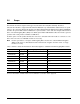
7.0 Physical/electrical specifications This section provides information relating to the physical and electrical characteristics of the drive. 7.1 AC power requirements None. 7.2 DC power requirements The voltage and current requirements for a single drive are shown below. Values indicated apply at the drive connector. Notes are shown following the last power requirements table.
Table 2: ST3600057FC DC power requirements 2 Gbit Notes Voltage 4 Gbit (Amps) (Amps) (Amps) (Amps) +5V +12V [2] +5V +12V [2] Regulation [5] ±5% ±5% [2] ±5% ±5% [2] Avg idle current DCX [1] [7] 0.39 0.81 0.42 0.81 Maximum starting current (peak DC) DC 3σ [3] 0.67 1.93 0.70 1.92 (peak AC) AC 3σ [3] 1.02 3.73 1.00 3.61 3σ [1] [4] 0.55 0.04 0.58 0.04 [1] [6] 0.48 1.18 0.51 1.17 [1] 0.50 1.19 0.53 1.19 1.30 3.00 1.32 2.
Table 4: ST3300657FC DC power requirements 2 Gbit Notes (Amps) Voltage 4 Gbit (Amps) (Amps) (Amps) +5V +12V [2] +5V +12V [2] Regulation [5] ±5% ±5% [2] ±5% ±5% [2] Avg idle current DCX [1] [7] 0.39 0.59 0.39 0.59 Maximum starting current (peak DC) DC 3σ [3] 0.62 1.91 0.62 1.91 (peak AC) AC 3σ [3] 0.96 3.75 0.98 3.57 3σ [1] [4] 0.56 0.04 0.56 0.04 [1] [6] 0.48 0.92 0.48 0.91 [1] 0.53 1.00 0.53 0.95 1.32 2.80 1.32 2.
7.2.1 Conducted noise immunity Noise is specified as a periodic and random distribution of frequencies covering a band from DC to 10 MHz. Maximum allowed noise values given below are peak-to-peak measurements and apply at the drive power connector. +5 V = +12 V = 250 mV pp from 0 to 20 MHz. 800 mV pp from 100 Hz to 8 KHz. 450 mV pp from 8 KHz to 20 KHz. 250 mV pp from 20 KHz to 5 MHz. 7.2.2 Power sequencing The drive does not require power sequencing.
Figure 2. Typical ST3450857FC current profiles Cheetah 15K.7 FC Product Manual, Rev.
Figure 3. Typical ST3300657FC current profiles 26 Cheetah 15K.7 FC Product Manual, Rev.
7.3 Power dissipation 600GB model Typical power dissipation under idle conditions in 4 Gbit operation is 11.58 watts (39.52 BTUs per hour). To obtain operating power for typical random read operations, refer to the following I/O rate curve (see Figure 4). Locate the typical I/O rate for a drive in your system on the horizontal axis and read the corresponding +5 volt current, +12 volt current, and total watts on the vertical axis. To calculate BTUs per hour, multiply watts by 3.4123. Figure 4.
450GB models Typical power dissipation under idle conditions in 4 Gbit operation is 10.24 watts (34.94 BTUs per hour). To obtain operating power for typical random read operations, refer to the following I/O rate curve (see Figure 4). Locate the typical I/O rate for a drive in your system on the horizontal axis and read the corresponding +5 volt current, +12 volt current, and total watts on the vertical axis. To calculate BTUs per hour, multiply watts by 3.4123. Figure 5.
300GB models Typical power dissipation under idle conditions in 4 Gbit operation is 9.06 watts (30.92 BTUs per hour). To obtain operating power for typical random read operations, refer to the following I/O rate curve (see Figure 4). Locate the typical I/O rate for a drive in your system on the horizontal axis and read the corresponding +5 volt current, +12 volt current, and total watts on the vertical axis. To calculate BTUs per hour, multiply watts by 3.4123. Figure 6.
b. Non-operating –40° to 158°F (–40° to 70°C) package ambient with a maximum gradient of 86°F (30°C) per hour. This specification assumes that the drive is packaged in the shipping container designed by Seagate for use with drive. HDA Temp. Check Point 1.0 " .5" Figure 7. Locations of the HDA temperature check point 7.4.2 Relative humidity The values below assume that no condensation on the drive occurs. a. Operating 5% to 95% non-condensing relative humidity with a maximum gradient of 20% per hour.
7.4.4 Shock and vibration Shock and vibration limits specified in this document are measured directly on the drive chassis. If the drive is installed in an enclosure to which the stated shock and/or vibration criteria is applied, resonances may occur internally to the enclosure resulting in drive movement in excess of the stated limits. If this situation is apparent, it may be necessary to modify the enclosure to minimize drive movement.
Z X Y Z Y X Figure 8. Recommended mounting 32 Cheetah 15K.7 FC Product Manual, Rev.
7.4.4.2 Vibration a. Operating—normal The drive as installed for normal operation, shall comply with the complete specified performance while subjected to continuous vibration not exceeding 10 – 300 Hz 301– 500 Hz 1.0 G RMS (0 to peak) 0.5 G RMS (0 to peak) Vibration may be applied in the X, Y, or Z axis. b.
7.4.7 Corrosive environment Seagate electronic drive components pass accelerated corrosion testing equivalent to 10 years exposure to light industrial environments containing sulfurous gases, chlorine and nitric oxide, classes G and H per ASTM B845. However, this accelerated testing cannot duplicate every potential application environment.
7.5 Mechanical specifications Refer to Figure 9 for detailed physical dimensions. See Section 11.4, “Drive mounting.”” Height: Width: Depth: Weight (max): 1.03 in 4.00 in 5.79 in 1.76 pounds 26.10 mm 101.60 mm 147 mm 0.80 kilograms B J H L K // T -Z- S REF -Z- [1] R REF N -XA -ZM C Notes: [1] Mounting holes are 6-32 UNC 2B, three on each side and four on the bottom. Max screw penetration into side of drive is 0.15 in. (3.81 mm). Max screw tightening torque is 6.0 in-lb (0.
8.0 About FIPS The Federal Information Processing Standard (FIPS) Publication 140-2, FIPS PUB 140-2, is a U.S. government computer security standard used to accredit cryptographic modules. It is titled “Security Requirements for Cryptographic Modules”. The initial publication was on May 25, 2001 and was last updated December 3, 2002.
9.0 About self-encrypting drives Self-encrypting drives (SEDs) offer encryption and security services for the protection of stored data, commonly known as “protection of data at rest.” These drives are compliant with the Trusted Computing Group (TCG) Enterprise Storage Specifications as detailed in Section 3.3. The Trusted Computing Group (TCG) is an organization sponsored and operated by companies in the computer, storage and digital communications industry.
9.2.2 Locking SP The Locking SP controls read/write access to the media and the cryptographic erase feature. Access to the Locking SP is available using the BandMasterX or EraseMaster passwords. Since the drive owner can define up to 16 data bands on the drive, each data band has its own password called BandMasterX where X is the number of the data band (0 through 15). 9.2.3 Default password When the drive is shipped from the factory, all passwords are set to the value of MSID.
9.6 Cryptographic erase A significant feature of SEDs is the ability to perform a cryptographic erase. This involves the host telling the drive to change the data encryption key for a particular band. Once changed, the data is no longer recoverable since it was written with one key and will be read using a different key. Since the drive overwrites the old key with the new one, and keeps no history of key changes, the user data can never be recovered.
10.0 Defect and error management Seagate continues to use innovative technologies to manage defects and errors. These technologies are designed to increase data integrity, perform drive self-maintenance, and validate proper drive operation. SCSI defect and error management involves drive internal defect/error management and FC system error considerations (errors in communications between the initiator and the drive).
read or re-write attempt. The maximum level used by the drive in LBA recovery is determined by the read and write retry counts. Table 5 equates the read and write retry count with the maximum possible recovery time for read and write recovery of individual LBAs. The times given do not include time taken to perform reallocations. Reallocations are performed when the ARRE bit (for reads) or AWRE bit (for writes) is one, the RC bit is zero, and the recovery time limit for the command has not yet been met.
Table 5: Read and write retry count maximum recovery times [1] Read retry count Maximum recovery time per LBA (cumulative, msec) Write retry count Maximum recovery time per LBA (cumulative, msec) 0 51.87 0 23.94 1 59.85 1 35.91 2 203.49 2 39.9 3 231.42 3 51.87 4 295.26 4 79.8 5 327.18 5 (default) 107.73 6 359.10 7 446.88 8 538.65 9 570.57 10 598.50 11 (default) 1,534.97 [1] These values are subject to change.
10.4 Background Media Scan Background Media Scan (BMS) is a self-initiated media scan. BMS is defined in the T10 document SPC-4 available from the T10 committee. BMS performs sequential reads across the entire pack of the media while the drive is idle. In RAID arrays, BMS allows hot spare drives to be scanned for defects prior to being put into service by the host system. On regular duty drives, if the host system makes use of the BMS Log Page, it can avoid placing data in suspect locations on the media.
10.7 Idle Read After Write Idle Read After Write (IRAW) utilizes idle time to verify the integrity of recently written data. During idle periods, no active system requests, the drive reads recently written data from the media and compares it to valid write command data resident in the drives data buffer. Any sectors that fail the comparison result in the invocation of a rewrite and auto-reallocation process. The process attempts to rewrite the data to the original location.
11.0 Installation Cheetah 15K.7 FC disc drive installation is a plug-and-play process. There are no jumpers, switches, or terminators on the drive. Simply plug the drive into the host’s 40-pin Fibre Channel backpanel connector (FCSCA)—no cables are required. See Section 12.5 for additional information about this connector. Use the FC-AL interface to select drive ID and all option configurations for devices on the loop.
11.3 Cooling The host enclosure must dissipate heat from the drive. You should confirm that the host enclosure is designed to ensure that the drive operates within the temperature measurement guidelines described in Section 7.4.1. In some cases, forced airflow may be required to keep temperatures at or below the temperatures specified in Section 7.4.1. If forced air is necessary, possible air-flow patterns are shown in Figure 11.
11.4 Drive mounting Mount the drive using the bottom or side mounting holes. If you mount the drive using the bottom holes, ensure that you do not physically distort the drive by attempting to mount it on a stiff, non-flat surface. The allowable mounting surface stiffness is 80 lb/in (14.0 N/mm).
12.0 Interface requirements This section partially describes the interface requirements as implemented on Cheetah 15K.7 FC drives. Additional information is provided in the Fibre Channel Interface Manual (part number 100293070). 12.1 FC-AL features This section lists the Fibre Channel-specific features supported by Cheetah 15K.7 FC drives. 12.1.1 Fibre Channel link service frames Table 6 lists the link services supported by Cheetah 15K.7 FC drives.
12.1.2 Fibre Channel task management functions Table 7 lists the Fibre Channel SCSI Fibre Channel Protocol (FC SCSI FCP) task management functions supported. Table 7: Fibre Channel SCSI FCP task management functions Task name Supported Terminate task No Clear ACA Yes Target reset Yes Clear task set Yes Abort task set Yes 12.1.3 Fibre Channel task management responses Table 8 lists the FC SCSI FCP response codes returned for task management functions supported.
12.1.4 Fibre Channel port login Table 9 identifies the required content of the N_Port Login (PLOGI) payload from an initiator.
12.1.5 Fibre Channel port login accept Table 10 identifies the N_Port Login access payload values.
12.1.7 Fibre Channel Process Login Accept Table 12 lists Cheetah 15K.7 FC process login accept payload data. Table 12: Process Login Accept (ACC) payload Bytes 0-15 02 10 00 14 16-31 00 00 00 12 12.1.8 08 00 21 00 00 00 00 00 00 00 00 00 Fibre Channel fabric login Table 13 lists the fabric login payload from the drive.
12.1.9 Fibre Channel fabric accept login Table 14 lists the required content of the Fabric Login Accept (ACC) payload from the fabric.
12.1.10 Fibre Channel Arbitrated Loop options Table 15 lists the FC-AL options supported by Cheetah 15K.7 FC drives. Table 15: FC-AL options supported Option Supported OPEN Half Duplex Accepted from another device. OPEN Full Duplex Sent to open another device. Accepted from another device. Private Loop Yes Public Loop Yes Old Port State No Loop Position Yes Loop Position Report Yes 12.2 Dual port support Cheetah 15K.7 FC drives have two independent FC-AL ports.
Table 16: Supported commands Executable state of standard SCSI commands in the presence of LBA banding (applies to SED models only) Affected LBA Unlocked ReadLock=Write Lock=False Affected LBA Locked ReadLock=Write Lock=True Executable Executable Command code Supported (Y/N) [4] Command name Affects entire Drive (Y/N) User Data Accessed (Y/N) 00h Y Test unit ready Y N 01h Y Rezero unit Y N Executable Executable 03h Y Request sense Y N Executable Executable Y Extended sense Y
Table 16: Supported commands (continued) Executable state of standard SCSI commands in the presence of LBA banding (applies to SED models only) Command code Supported (Y/N) [4] Command name Affects entire Drive (Y/N) User Data Accessed (Y/N) Affected LBA Unlocked ReadLock=Write Lock=False Affected LBA Locked ReadLock=Write Lock=True Y Power control page (1Ah) Y Information exceptions control page (1Ch) Y Background Scan mode subpage (01h) 1Bh Y Start unit/stop unit Y Y Executable Execut
Table 16: Supported commands (continued) Executable state of standard SCSI commands in the presence of LBA banding (applies to SED models only) Command code Supported (Y/N) [4] Command name 3Ah N Copy and verify 3Bh Y Write buffer Affects entire Drive (Y/N) User Data Accessed (Y/N) Affected LBA Unlocked ReadLock=Write Lock=False Affected LBA Locked ReadLock=Write Lock=True N Y Check Condition Check Condition (all modes except modes 4h - 7h, 0Eh, and 0Fh) Y N Executable Executable (mod
Table 16: Supported commands (continued) Executable state of standard SCSI commands in the presence of LBA banding (applies to SED models only) Command code Supported (Y/N) [4] Command name Y Background Medium Scan page (15h) Y Cache Statistics Counter page (37h) Y Factory Log page (3Eh) 4E-4Fh N Not used 50h N XD write 51h N XP write 52h N XD read 53-54h N Not used 55h Y Mode Select (10) [3] 56h Y Reserved (10) Y 3rd party reserve N Extent reservation 57h Y Released (1
[3] [4] Reference Mode Sense command 1Ah for mode pages supported. Y = Yes. Command is supported. N = No. Command is not supported. A = Support is available on special request. 12.3.1 Inquiry data Table 17 lists the Inquiry command data that the drive should return to the initiator per the format given in the Fibre Channel Interface Manual. Table 17: Bytes Cheetah 15K.
On drives requiring unique saved values, the required unique saved values are stored into the saved values storage location on the media prior to shipping the drive. Some drives may have unique firmware with unique default values also. On standard OEM drives, the saved values are taken from the default values list and stored into the saved values storage location on the media prior to shipping. 3. Current values Current values are volatile values being used by the drive to control its operation.
Table 18: Mode Sense data saved, default and changeable values for ST3600057FC drives MODE DATA HEADER: 00 be 00 10 00 00 00 08 MODE PAGES: DEF CHG 81 0a c0 0b ff 00 00 00 05 00 ff ff 81 0a ff ff 00 00 00 00 ff 00 ff ff DEF CHG 82 0e 80 80 00 00 00 00 00 00 01 3a 00 00 00 00 82 0e ff ff 00 00 00 00 00 00 ff ff 00 00 00 00 DEF CHG 83 16 bb d0 00 00 00 00 03 80 04 c4 02 00 00 01 00 c0 00 4c 40 00 00 00 83 16 00 00 00 00 00 00 00 00 00 00 00 00 00 00 00 00 00 00 00 00 00 00 DEF CHG 84 16 01 8a 9a 08 0
Table 19: Mode Sense data default and changeable values for ST3450857FC drives MODE DATA HEADER: 00 be 00 10 00 00 00 08 BLOCK DESCRIPTOR: 34 65 f8 70 00 00 02 00 MODE PAGES: DEF CHG 81 0a c0 0b ff 00 00 00 05 00 ff ff 81 0a ff ff 00 00 00 00 ff 00 ff ff DEF CHG 82 0e 80 80 00 00 00 00 00 00 01 3a 00 00 00 00 82 0e ff ff 00 00 00 00 00 00 ff ff 00 00 00 00 DEF CHG 83 16 bb d0 00 00 00 00 03 80 04 c4 02 00 00 01 00 c0 00 4c 40 00 00 00 83 16 00 00 00 00 00 00 00 00 00 00 00 00 00 00 00 00 00 00 00 00
Table 20: Mode Sense data default and changeable values for ST3300657FC drives MODE DATA HEADER: 00 be 00 10 00 00 00 08 BLOCK DESCRIPTOR: 22 ec b2 5c 00 00 02 00 MODE PAGES: DEF CHG 81 0a c0 0b ff 00 00 00 05 00 ff ff 81 0a ff ff 00 00 00 00 ff 00 ff ff DEF CHG 82 0e 80 80 00 00 00 00 00 00 01 3a 00 00 00 00 82 0e ff ff 00 00 00 00 00 00 ff ff 00 00 00 00 DEF CHG 83 16 bb d0 00 00 00 00 03 80 04 c4 02 00 00 01 00 c0 00 4c 40 00 00 00 83 16 00 00 00 00 00 00 00 00 00 00 00 00 00 00 00 00 00 00 00 00
12.4 Miscellaneous operating features and conditions Table 21 lists various features and conditions. A “Y” in the support column indicates the feature or condition is supported. An “N” in the support column indicates the feature or condition is not supported.
12.5 FC-AL physical interface Figure 12 shows the location of the J1 Fibre Channel single connection attachment (FC-SCA). Figure 14 provides the dimensions of the FC-SCA connector. Details of the physical, electrical, and logical characteristics are provided within this section. The operational aspects of Seagate’s Fibre Channel drives are provided in the Fibre Channel Interface Manual.. J1 interface connector Figure 12. Physical interface 12.5.
12.5.2 Connector requirements Table 23: Recommended mating SCA part numbers Part description Positions Part number Features AMP Vertical (SCA sequence) 40 787317-1 With polarization Berg 40 71781 With polarization Methode 40 512-220-91-101N With polarization Molex 40 717431040 With polarization The FC-AL SCA device connector is illustrated in Figure 14. 1.618 ± .003 in (41.1 ± 0.08 mm) Pin 20 Pin 40 Pin 1 Pin 21 .64 in (16.24 mm) 0.197 ± .003 in 2 places (5.00 ± .08 mm) 1.
Table 24: FC-SCA pin descriptions Pin Signal name Signal type Pin Signal name 1* -EN bypass port A Low Voltage TTL output 21 12 Volts charge 2* 12 Volts 22 Ground 3* 12 Volts 23 Ground 4* 12 Volts 24* +Port A_in 5* -Parallel ESI 25* -Port A_in 6* Ground[1] 26 Ground 7* Active LED out 27* +Port B_in 8* Reserved 28* -Port B_in 9* [2] TTL input 29 Ground [2] Start_1 Open collector out Signal type FC Diff. input pair FC Diff.
12.5.6 Power Power is supplied through the FC-SCA with support for +5 volts and +12 volts. All of the voltage pins in the drive connector are the same length. Four 12 volt pins provide +12 volt power to the drive. The current return for the +12 volt power supply is through the common ground pins. The supply current and return current must be distributed as evenly as possible among the pins. The maximum current typically occurs while the drive motor is starting.
12.5.8 Active LED Out The Active LED Out signal is driven by the drive as indicated in Table 25.
12.5.11 SEL_6 through SEL_0 ID lines The SEL_6 through SEL_0 ID lines determine drive address, and, optionally, for an Enclosure Services Interface. When the Parallel ESI line is high, the enclosure backpanel must provide address information on the SEL line. Refer to table 27 for a mapping of SEL to FC-AL physical addresses (AL_PA). You can think of the SEL lines as the equivalent of a backpanel logic plug. The drives does not provide pull up resistors on these lines.
Table 27: Arbitrated loop physical address (AL_PA) values AL_PA (hex) SEL ID (hex) Setting (dec) AL_PA (hex) SEL ID (hex) Setting (dec) AL_PA (hex) SEL ID (hex) Setting (dec) EF E8 E4 E2 00 01 02 03 00 01 02 03 A3 9F 9E 9D 2B 2C 2D 2E 43 44 45 46 4D 4C 4B 4A 56 57 58 59 86 87 88 89 E1 E0 DC DA D9 D6 D5 D4 D3 D2 04 05 06 07 08 09 0A 0B 0C 0D 04 05 06 07 08 09 10 11 12 13 9B 98 97 90 8F 88 84 82 81 80 2F 30 31 32 33 34 35 36 37 38 47 48 49 50 51 52 53 54 55 56 49 47 46 45 43 3c 3A 39
12.5.12 Device control codes The drive inputs a Device Control Code on the DEV_CTRL_CODE lines at power up to determine the link rate on the Fibre Channel ports. Both ports run at the same rate. If the backpanel does not connect to these lines, the drive has 10K ohm pull up resistors that default the device control code to 7 (1.0625 GHz). Table lists the supported codes. Table 28: Device control code values 2 (pin 17) 1 (pin 18) 0 (pin 39) Definition 0 0 0 Reserved for power failure warning.
12.6.2 LED driver signals Fault and Active LED signals are located in the FC-SCA connector (J1). See Table 30 for the output characteristics of the LED drive signals. Table 30: LED drive signal State Current drive available LED off, high 0 < IOH < 100µA LED on, low IOL < -30 mA 12.6.3 Output voltage 0 < VOL < 0.8V FC Differential output The serial output signal voltage characteristics are provided in Table 31.
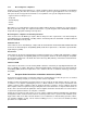
Figure 17 provides the data valid eye diagram for typical and minimum requirements to recover data at the specified interface error rate. The inputs are AC coupled on the drive. Vin (mv) 941 ps 659 ps Typical 376 ps Minimum Figure 17. Receive eye diagram Table 33: Eye diagram data values Link rate 1 GHz 2 GHz 4 GHz Bit time 941 ps 470 ps 235 ps XMIT eye 725 ps min. 315 ps min. 1581/1132 Typical 659 ps 305 ps 145 ps Minimum 395 ps 226 ps 113 ps RCV eye 1. 2. 74 Short Ideal load.
Index Numerics 12 volt pins 68 3rd party reserve command 58 5 volt pins 68 A Abort Sequence (ABTS) 48 abort task set function 49 AC coupling 67 AC power requirements 21 ACA active status 64 ACA active, faulted initiator status 64 Accept (ACC) 48 acoustics 33 active LED Out signal 69 Actual retry count bytes command 55 actuator assembly design 6 adaptive caching 64 Address Discovery (ADISC) 48 addresses 65 Admin SP 37 AES-128 data encryption 37 AFR 14 air cleanliness 33 air flow 46 illustrated 46 Alternate
Cryptographic erase 39 CS 50 Current profiles 24 customer service 20 drivers and receivers 7 dual port support 54 D electrical description of connector 66 signal characteristics 72 specifications 21 electromagnetic compatibility 3 electromagnetic susceptibility 34 EMI requirements 3 enable bypass port A 69 port B 69 signal 69 state 15 Enclosure Services interface 66 Enclosure services page command 56 encryption engine 37 encryption key 38 environmental limits 29 requirements 14 environmental control 33 E
FCP for SCSI, document 5 response codes 49 task management functions 49 FC-PH document 5 FDE features 7 features 7 interface 48 Fibre Channel documents 5 Fibre Channel Interface Control page (19h) 55 Fibre Channel Interface Manual 2, 3 Fibre Channel Services 48 Field pointer bytes command 55 FIPS 36 firmware 7 corruption 58 Firmware download option command 57 firmware download port 38 Firmware numbers page command 55 flawed sector reallocation 7 FLOGI received on Port A 52 received on Port B 52 Force unit a
FC-AL options 54 loop position report FC-AL options 54 LS_RJT 50, 53 LSI circuitry 8 M maintenance 14 Makers Secure ID 37 maximum delayed motor start 22, 23 maximum start current 22, 23 mean time between failure (MTBF) 15 media description 8 Media Pre-Scan 43 miscellaneous feature support Adaptive caching 64 Asynchronous event notification 64 Automatic contingent allegiance 64 Deferred error handling 64 FC-AL selective reset 64 Parameter rounding 64 Queue tagging 64 Reporting actual retry count 64 Segmente
performance degradation 31 performance highlights 8 physical damage 33 physical interface 65 description 65 physical specifications 21 PI 51, 52 pin descriptions 66 PN 50, 53 port bypass circuit 15, 65, 69 Port DISCovery 50 Port Discovery (PDISC) 48 port identifier field 51, 52 port login 50 accept 51 Port Name 53 Port name (initiator’s) 50 power 68 dissipation 27 requirements, AC 21 requirements, DC 21 sequencing 24 Power control page (1Ah) command 56 power distribution 3 power failure warning 72 PowerCycl
security partitions 37 Security Protocol In 37 Security Protocol Out 37 Seek command 55 seek error defined 15 rate 14 Seek extended command 56 seek performance characteristics 10 seek time average typical 10 full stroke typical 10 single track typical 10 segmented caching 64 SEL ID 45 lines 70 standard feature 7 Self-Encrypting Drive (SED) Users Guide 2 self-encrypting drives 37 Self-Monitoring Analysis and Reporting Technology 8, 16 Send diagnostics page command 56 Sequential delivery 50, 53 Service Option
Write buffer command 57 Write combined header and data mode (0) 57 Write command 55 Write data mode (2) 57 Write extended command 56 Write long command 57 Write same command 57, 58 X XD read 58 XD write 58 XD write extended command 58 XID reassign 50 XP write 58 Z zero latency read 64 zone bit recording (ZBR) 7 Cheetah 15K.7 FC Product Manual, Rev.
82 Cheetah 15K.7 FC Product Manual, Rev.
Seagate Technology LLC 920 Disc Drive, Scotts Valley, California 95066-4544, USA Publication Number: 100516225, Rev.