Product Manual Cheetah NS 10K.2 SAS ® ST3600002SS ST3450802SS 100516228 Rev.
Copyright © 2009 Seagate Technology LLC. All rights reserved. Printed in U.S.A. Publication number: 100516228, Rev. C, November 2009 Seagate, Seagate Technology and the Wave logo are registered trademarks of Seagate Technology LLC in the United States and/or other countries. Cheetah, SeaTools and SeaTDD are either trademarks or registered trademarks of Seagate Technology LLC or one of its affiliated companies in the United States and/or other countries.
Contents 1.0 Scope. . . . . . . . . . . . . . . . . . . . . . . . . . . . . . . . . . . . . . . . . . . . . . . . . . . . . . . . . . . . . . . . . . . . . . . . 1 2.0 Standards, compliance and reference documents . . . . . . . . . . . . . . . . . . . . . . . . . . . . . . . . . . . 2.1 Standards . . . . . . . . . . . . . . . . . . . . . . . . . . . . . . . . . . . . . . . . . . . . . . . . . . . . . . . . . . . . . . 2.1.1 Electromagnetic compatibility. . . . . . . . . . . . . . . . . . . . . . . . . .
6.4.2 Relative humidity . . . . . . . . . . . . . . . . . . . . . . . . . . . . . . . . . . . . . . . . . . . . . . . . 6.4.3 Effective altitude (sea level) . . . . . . . . . . . . . . . . . . . . . . . . . . . . . . . . . . . . . . . . 6.4.4 Shock and vibration . . . . . . . . . . . . . . . . . . . . . . . . . . . . . . . . . . . . . . . . . . . . . . 6.4.5 Acoustics . . . . . . . . . . . . . . . . . . . . . . . . . . . . . . . . . . . . . . . . . . . . . . . . . . . . . . 6.4.6 Air cleanliness . . . . . .
1.0 Scope This manual describes Seagate Technology® LLC, Cheetah® NS 10K.2 SAS (Serial Attached SCSI) disk drives. Cheetah drives support the SAS Protocol specifications to the extent described in this manual. The SAS Interface Manual (part number 100293071) describes the general SAS characteristics of Cheetah® NS 10K.2 SAS and other Seagate SAS drives. Cheetah NS 10K.2 SAS Product Manual, Rev.
2.0 Standards, compliance and reference documents The drive has been developed as a system peripheral to the highest standards of design and construction. The drive depends on its host equipment to provide adequate power and environment for optimum performance and compliance with applicable industry and governmental regulations. Special attention must be given in the areas of safety, power distribution, shielding, audible noise control, and temperature regulation.
2.2 Compliance 2.2.1 Electromagnetic compliance Seagate uses an independent laboratory to confirm compliance with the directives/standards for CE Marking and C-Tick Marking. The drive was tested in a representative system for typical applications. The selected system represents the most popular characteristics for test platforms. The system configurations include: • • • • • • • Typical current use microprocessor 3.
2.3 Reference documents SCSI Commands Reference Manual Seagate part number: 100293068 SAS Interface Manual Seagate part number: 100293071 Applicable ANSI SAS documents SFF-8323 3.5” Drive Form Factor with Serial Connector SFF-8460 HSS Backplane Design Guidelines SFF-8470 Multi Lane Copper Connector SFF-8482 SAS Plug Connector ANSI INCITS.
3.0 General description Cheetah® NS 10K.2 SAS drives provide high performance, high capacity data storage for a variety of systems including engineering workstations, network servers, mainframes, and supercomputers. The Serial Attached SCSI interface is designed to meet next-generation computing demands for performance, scalability, flexibility and high-density storage requirements.
3.1 Standard features Cheetah NS SAS drives have the following standard features: • • • • • • • • • • • • • • • • • • • • • • • • • • Perpendicular recording technology 1.5 / 3 / 6 Gb Serial Attached SCSI (SAS) interface Integrated dual port SAS controller Support for SAS expanders and fanout adapters Downloadable firmware using the SAS interface 128 - deep task set (queue) Supports up to 32 initiators Jumperless configuration.
3.5 Formatted capacities Standard OEM models are formatted to 512 bytes per block. The block size is selectable at format time and must be a multiple of 4 bytes. Users having the necessary equipment may modify the data block size before issuing a format command and obtain different formatted capacities than those listed. To provide a stable target capacity environment and at the same time provide users with flexibility if they choose, Seagate recommends product planning in one of two modes: 1.
4.0 Performance characteristics This section provides detailed information concerning performance-related characteristics and features of Cheetah NS SAS drives. 4.1 Internal drive characteristics Drive capacity Read/write data heads Tracks per inch Peak bits per inch Areal Density Internal data rate Disk rotation speed Avg rotational latency ST3600002SS 600 8 165,000 1,347 225 1.01 to 1.84 10K 2.98 ST3450802SS 450 6 165,000 1,347 225 1.01 to 1.84 10K 2.
4.2.2 Format command execution time (minutes) ST3600002SS ST3450802SS Maximum (with verify) 182 129 Maximum (without verify) 101 68 Execution time measured from receipt of the last byte of the Command Descriptor Block (CDB) to the request for a Status Byte Transfer to the Initiator (excluding connect/disconnect). When changing sector sizes, the format times shown above may need to be increased by 30 minutes. 4.2.
4.4 Prefetch/multi-segmented cache control The drive provides a prefetch (read look-ahead) and multi-segmented cache control algorithms that in many cases can enhance system performance. Cache refers to the drive buffer storage space when it is used in cache operations. To select this feature, the host sends the Mode Select command with the proper values in the applicable bytes in page 08h.
The buffer segmentation scheme is set up or changed independently, having nothing to do with the state of RCD. When a write command is issued, if RCD=0, the cache is first checked to see if any logical blocks that are to be written are already stored in the cache from a previous read or write command. If there are, the respective cache segments are cleared. The new data is cached for subsequent Read commands.
5.0 Reliability specifications The following reliability specifications assume correct host and drive operational interface, including all interface timings, power supply voltages, environmental requirements and drive mounting constraints. Seek error rate: Read Error Rates1 Recovered Data Unrecovered Data Miscorrected Data Interface error rate: MTBF Annualized Failure Rate (AFR) Preventive maintenance: 1.
a seek positioning error (Error code = 15h or 02h) will be reported with a Hardware error (04h) in the Sense Key. Recoverable seek errors are specified at Less than 10 errors in 108 seeks. Unrecoverable seek errors (Sense Key = 04h) are classified as drive failures. 5.1.4 Interface errors An interface error is defined as a failure of the receiver on a port to recover the data as transmitted by the device port connected to the receiver.
5.2.4 S.M.A.R.T. S.M.A.R.T. is an acronym for Self-Monitoring Analysis and Reporting Technology. This technology is intended to recognize conditions that indicate imminent drive failure and is designed to provide sufficient warning of a failure to allow you to back up the data before an actual failure occurs. Note. The drive’s firmware monitors specific attributes for degradation over time but can’t predict instantaneous drive failures.
the interval expires, the error rate is considered to be unacceptable. If the number of errors does not exceed the threshold before the interval expires, the error rate is considered to be acceptable. In either case, the interval and failure counters are reset and the process starts over. Predictive failures S.M.A.R.T. signals predictive failures when the drive is performing unacceptably for a period of time.
The most thorough option is the extended test that performs various tests on the drive and scans every logical block address (LBA) of the drive. The short test is time-restricted and limited in length—it does not scan the entire media surface, but does some fundamental tests and scans portions of the media. If DST encounters an error during either of these tests, it reports a fault condition. If the drive fails the test, remove it from service and return it to Seagate for service. 5.2.7.
Each test consists of three segments: an electrical test segment, a servo test segment, and a read/verify scan segment. Short test (Function Code: 001b) The purpose of the short test is to provide a time-limited test that tests as much of the drive as possible within 120 seconds. The short test does not scan the entire media surface, but does some fundamental tests and scans portions of the media. A complete read/verify scan is not performed and only factual failures will report a fault condition.
warranty information, refer to the standard terms and conditions of purchase for Seagate products on your purchase documentation. The remaining warranty for a particular drive can be determined by calling Seagate Customer Service at 1-800-468-3472. You can also determine remaining warranty using the Seagate web site (www.seagate.com). The drive serial number is required to determine remaining warranty information. Shipping When transporting or shipping a drive, use only a Seagate-approved container.
6.0 Physical/electrical specifications This section provides information relating to the physical and electrical characteristics of the drive. 6.1 AC power requirements None. 6.2 DC power requirements The voltage and current requirements for a single drive are shown below. Values indicated apply at the drive connector. Table 12: ST3600002SS DC power requirements Notes Voltage 1.
[6] transient response. During idle, the drive heads are relocated every 60 seconds to a random location within the band from three-quarters to maximum track. Table 13: ST3450802SS DC power requirements Notes Voltage 1.5 Gb mode 3 Gb mode 6 Gb mode (Amps) (Amps) (Amps) (Amps) (Amps) (Amps) +5V +12V [2] +5V +12V [2] +5V +12V [2] Regulation [5] ±5% ±5% [2] ±5% ±5% [2] ±5% ±5% [2] Avg idle current DCX [1] [6] 0.36 0.33 0.38 0.32 0.32 0.
6.2.1 Conducted noise immunity Noise is specified as a periodic and random distribution of frequencies covering a band from DC to 10 MHz. Maximum allowed noise values given below are peak-to-peak measurements and apply at the drive power connector. +5V = 250 mV pp from 0 to 100 kHz to 20 MHz +12V = 800 mV pp from 100 Hz to 8 KHz 450 mV pp from 8 KHz to 20 KHz 250 mV pp from 20 KHz to 5 MHz 6.2.2 Power sequencing The drive does not require power sequencing.
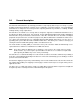
Figure 1. Typical ST3600002SS drive +5V and +12V current profiles Figure 2. Typical ST3450802SS drive +5V and +12V current profiles 22 Cheetah NS 10K.2 SAS Product Manual, Rev.
6.3 Power dissipation ST3600002SS Typical power dissipation under idle conditions in 6Gb operation is 10.03W (34.23 BTUs per hour) To obtain operating power for typical random read operations, refer to the following I/O rate curve (see Figure 3). Locate the typical I/O rate for a drive in your system on the horizontal axis and read the corresponding +5 volt current, +12 volt current, and total watts on the vertical axis. To calculate BTUs per hour, multiply watts by 3.4123.
6.4 Environmental limits Temperature and humidity values experienced by the drive must be such that condensation does not occur on any drive part. Altitude and atmospheric pressure specifications are referenced to a standard day at 58.7°F (14.8°C). Maximum wet bulb temperature is 82°F (28°C). 6.4.1 Temperature a. Operating The maximum allowable continuous or sustained HDA case temperature for the rated Annualized Failure Rate (AFR) is 122°F (50°C) The maximum allowable HDA case temperature is 60°C.
6.4.2 Relative humidity The values below assume that no condensation on the drive occurs. a. Operating 5% to 95% non-condensing relative humidity with a maximum gradient of 20% per hour. b. Non-operating 5% to 95% non-condensing relative humidity. 6.4.3 Effective altitude (sea level) a. Operating –1,000 to +10,000 feet (–305 to +3,048 meters) b. Non-operating –1,000 to +40,000 feet (–305 to +12,192 meters) 6.4.
d. Packaged Disk drives shipped as loose load (not palletized) general freight will be packaged to withstand drops from heights as defined in the table below. For additional details refer to Seagate specifications 30190-001 (under 100 lbs/45 kg) or 30191-001 (over 100 lbs/45 Kg). Package size Packaged/product weight Drop height <600 cu in (<9,800 cu cm) 600-1800 cu in (9,800-19,700 cu cm) >1800 cu in (>19,700 cu cm) >600 cu in (>9,800 cu cm) Any 0-20 lb (0 to 9.1 kg) 0-20 lb (0 to 9.1 kg) 20-40 lb (9.
6.4.4.2 Vibration a. Operating—normal The drive as installed for normal operation, shall comply with the complete specified performance while subjected to continuous vibration not exceeding 10 - 300 Hz 301 - 500 Hz 1.0 G RMS (0 to peak) 0.5 G RMS (0 to peak) Vibration may be applied in the X, Y, or Z axis. b.
exposed to an ambient relative humidity greater than 95%. Materials used in cabinet fabrication, such as vulcanized rubber, that can outgas corrosive compounds should be minimized or eliminated. The useful life of any electronic equipment may be extended by replacing materials near circuitry with sulfide-free alternatives. 6.4.
6.5 Mechanical specifications Refer to Figure 7 for detailed physical dimensions. See Section 8.3, “Drive mounting.” Height: Width: Depth: Weight: Figure 7. 1.013 in 3.999 in 5.769 in 1.482 lb 25.73 mm 101.57 mm 146.53 mm 0.672 kg Physical dimensions Cheetah NS 10K.2 SAS Product Manual, Rev.
7.0 Defect and error management Seagate continues to use innovative technologies to manage defects and errors. These technologies are designed to increase data integrity, perform drive self-maintenance, and validate proper drive operation. SCSI defect and error management involves drive internal defect/error management and SAS system error considerations (errors in communications between the initiator and the drive).
read or re-write attempt. The maximum level used by the drive in LBA recovery is determined by the read and write retry counts. Table 14 equates the read and write retry count with the maximum possible recovery time for read and write recovery of individual LBAs. The times given do not include time taken to perform reallocations. Reallocations are performed when the ARRE bit (for reads) or AWRE bit (for writes) is one, the RC bit is zero, and the recovery time limit for the command has not yet been met.
7.3 SAS system errors Information on the reporting of operational errors or faults across the interface is given in the SAS Interface Manual. The SSP Response returns information to the host about numerous kinds of errors or faults. The Receive Diagnostic Results reports the results of diagnostic operations performed by the drive. Status returned by the drive to the initiator is described in the SAS Interface Manual.
ations performed by the drive. When a write command is received for an LBA marked for DAR, the auto-reallocation process is invoked and attempts to rewrite the data to the original location. If a verification of this rewrite fails, the sector is re-mapped to a spare location. This is in contrast to the system having to use the Reassign Command to reassign a location that was unreadable and then generate a write command to rewrite the data.
8.0 Installation Cheetah disk drive installation is a plug-and-play process. There are no jumpers, switches, or terminators on the drive. SAS drives are designed to be used in a host system that provides a SAS-compatible backplane with bays designed to accommodate the drive. In such systems, the host system typically provides a carrier or tray into which you need to mount the drive. Mount the drive to the carrier or tray provided by the host system using four 6-32 UNC screws.
8.2 Cooling The host enclosure must dissipate heat from the drive. You should confirm that the host enclosure is designed to ensure that the drive operates within the temperature measurement guidelines described in Section 6.4.1. In some cases, forced airflow may be required to keep temperatures at or below the temperatures specified in Section 6.4.1. If forced air is necessary, possible air-flow patterns are shown in Figure 9.
8.3 Drive mounting Mount the drive using the bottom or side mounting holes. If you mount the drive using the bottom holes, ensure that you do not physically distort the drive by attempting to mount it on a stiff, non-flat surface. The allowable mounting surface stiffness is 80 lb/in (14.0 N/mm).
9.0 Interface requirements This section partially describes the interface requirements as implemented on Cheetah drives. Additional information is provided in the SAS Interface Manual (part number 100293071). 9.1 SAS features This section lists the SAS-specific features supported by Cheetah® NS 10K.2 SAS drives. 9.1.1 task management functions Table 15 lists the SAS task management functions supported.
9.2 Dual port support Cheetah SAS drives have two independent ports. These ports may be connected in the same or different SCSI domains. Each drive port has a unique SAS address. The two ports run at the same link rate. The first port to successfully complete speed negotiation sets the link rate support by both ports. When the second port participates in speed negotiation, it indicates the only supported speed is the speed selected by the first port.
9.3 SCSI commands supported Table 17 lists the SCSI commands supported by Cheetah drives. Table 17: Commands supported by Cheetah® NS 10K.
Table 17: Commands supported by Cheetah® NS 10K.
Table 17: Commands supported by Cheetah® NS 10K.
Table 17: Commands supported by Cheetah® NS 10K.2 SAS family drives (continued) Command name Command code FUA bit Supported Y Write Long 3Fh Y Write Same 41h Y PBdata N LBdata N XDRead 52h N XDWrite 50h N XPWrite 51h N [1] [2] [3] [4] 42 Cheetah NS drives can format to 512, 520, 524, or 528 bytes per logical block. Warning. Power loss during flash programming can result in firmware corruption. This usually makes the drive inoperable.
9.3.1 Inquiry data Table 18 lists the Inquiry command data that the drive should return to the initiator per the format given in the SAS Interface Manual.
On drives requiring unique saved values, the required unique saved values are stored into the saved values storage location on the media prior to shipping the drive. Some drives may have unique firmware with unique default values also. On standard OEM drives, the saved values are taken from the default values list and stored into the saved values storage location on the media prior to shipping. 3. Current values Current values are volatile values being used by the drive to control its operation.
9.3.2.
9.3.2.
9.4 Miscellaneous operating features and conditions Table 19 lists various features and conditions. A “Y” in the support column indicates the feature or condition is supported. An “N” in the support column indicates the feature or condition is not supported.
9.4.1 SAS physical interface Figure 10 shows the location of the SAS device connector J1. Figures 11 and 12 provide the dimensions of the SAS device. Details of the physical, electrical, and logical characteristics are provided within this section. The operational aspects of Seagate’s SAS drives are provided in the SAS Interface Manual. The SAS connector complies with SFF-8482. SAS Interface connector Figure 10. 48 Physical interface Cheetah NS 10K.2 SAS Product Manual, Rev.
0.80 (6X) 5.92 7.62 4.65 0.52 2.00 (3X) 0.45 5.08 0.08 x 45 0.03 (7X) 0.10 M E 42.73 REF. 41.13 0.30 0.15 0.20 B 0.05 (2X) C A B 4.00 1.10 0.08 0.15 D 0.30 CL OF DATUM D 0.05 (4X) A B R0.30 C 0.08 (4X) SEE Detail1 33.43 0.05 B 15.875 15.875 1.27 (14X) 1.27 (6X) 0.84 5.08 0.05 (22X) 0.15 B 4.90 0.08 0.35MIN P15 P1 S7 S1 CL OF DATUM B Figure 11. SAS connector dimensions Cheetah NS 10K.2 SAS Product Manual, Rev.
Detail A 6.10 S14 2.25 S8 0.05 x 45 (5X) 0.05 0.40 4.85 0.30 0.05 0.10 B 0.05 X 45 (3X) CORING ALLOWED IN THIS AREA. E 4.40 0.15 R0.30 0.08 SEE Detail 2 C 1.95 0.08 A 45 0.35 3.90 0.05 0.15 SECTION C - C SECTION A - A 0.08 0.05 CONTACT SURFACE FLUSH TO DATUM A 0.03 65 1.23 0.05 0.08 1.90 0.08 30 0.05 Detail 2 2.40 0.08 0.10 A SECTION B - B D Figure 12. SAS connector dimensions 9.4.2 Physical characteristics This section defines physical interface connector. 9.4.
9.4.4 Electrical description SAS drives use the device connector for: • DC power • SAS interface • Activity LED This connector is designed to either plug directly into a backpanel or accept cables. 9.4.5 Pin descriptions This section provides a pin-out of the SAS device and a description of the functions provided by the pins. Table 21: SAS pin descriptions Pin Signal name S1 Port A Ground S2* +Port A_in S3* Signal type Pin Signal name P1* NC (reserved 3.3Volts) P2* NC (reserved 3.
9.4.6 SAS transmitters and receivers A typical SAS differential copper transmitter and receiver pair is shown in Figure 13. The receiver is AC coupling to eliminate ground shift noise. TX .01 RX .01 Receiver 100 RY Differential Transfer Medium Transmitter 100 TY Figure 13. SAS transmitters and receivers 9.4.7 Power The drive receives power (+5 volts and +12 volts) through the SAS device connector. Three +12 volt pins provide power to the drive, 2 short and 1 long.
The Ready LED Out signal is designed to pull down the cathode of an LED. The anode is attached to the proper +3.3 volt supply through an appropriate current limiting resistor. The LED and the current limiting resistor are external to the drive. See Table 23 for the output characteristics of the LED drive signals. Table 23: LED drive signal State Test condition Output voltage LED off, high 0 V ≤VOH ≤3.6 V -100 µA < IOH < 100 µA LED on, low IOL = 15 mA 0 ≤VOL ≤0.225 V 9.5.
9.5.2.1.2 Receive eye mask Figure 14 describes the receive eye mask. This eye mask applies to jitter after the application of a single pole high-pass frequency-weighting function that progressively attenuates jitter at 20 dB/decade below a frequency of ((bit rate) / 1.667). Figure 14. Receive eye mask Verifying compliance with the limits represented by the receive eye mask should be done with reverse channel traffic present in order that the effects of crosstalk are taken into account. 9.5.2.1.
The leading and trailing edge slopes of figure 14 shall be preserved.
9.5.2.2 Transmitter signal characteristics Table 25 specifies the signal requirements at the transmitter end of a TxRx connection as measured into the zero-length test load. All specifications are based on differential measurements. The OOB sequence is performed at signal voltage levels corresponding to the lowest supported transfer rate. Table 25 specifies the signal characteristics. Table 25: Transmitter signal characteristics Signal characteristica Units 1.5Gb/s 3.
9.5.2.3 Receiver signal characteristics Table 26 defines the compliance point requirements of the signal at the receiver end of a TxRx connection as measured into the test loads specified in figure 17 and figure 18. Table 26: Receiver signal characteristics Signal characteristic Units 1.5Gb/s 3.0Gb/s Jitter (see figure 14)b N/A See table 27 See table 27 2 x Z2 mV(P-P) 1,200 1,600 2 x Z1 mV(P-P) 325 275 UI 0.275 0.275 X2 UI 0.50 0.50 Skewd ps 80 75 mV(P-P) 2.000 2.
9.5.2.3.2 Receiver jitter tolerance Table 28 defines the amount of jitter the receiver shall tolerate. Table 28: Receiver jitter tolerance 1.5Gb/sa 3.0Gb/sa Sinusoidal jitterb,c Deterministic jittere,f,h Total jitterh Sinusoidal jitterb,d Deterministic jittere,g,h Total jitterh 0.10 0.35 0.65 0.10 0.35 0.65 a Units are in UI.
Table 29: Impedance requirements (Sheet 2 of 2) Requirement Common mode impedanceb,e Units 1.5Gb/s 3.0Gb/s ohm 20 min/40 max 20 min/40 max ohm 60 min/115 max 60 min/115 max ohm 5 5 ohm 15 min/40 max 15 min/40 max Transmitter source termination Differential impedanceb Differential impedance imbalanceb,g b Common mode impedance a All times indicated for time domain reflectometer measurements are recorded times.
mitter signal at the test points on the required test loads. The transmitter uses the same settings (e.g., preemphasis, voltage swing) with both the zero-length test load and the TCTF test load. The signal specifications at IR are met under each of these loading conditions. The TCTF is the mathematical statement of the transfer function through which the transmitter shall be capable of producing acceptable signals as defined by a receive mask.
Figure 18 shows the zero-length test load. Figure 18. Zero-length test load Figure 19 shows an ISI loss example at 3.0Gb/s. Figure 19. ISI loss example at 3.0Gb/s Figure 20 shows an ISI loss example at 1.5Gb/s. Figure 20. ISI loss example at 1.5Gb/s Cheetah NS 10K.2 SAS Product Manual, Rev.
9.5.2.5 Receiver characteristics The drive receiver is A.C. coupled. The receive network terminates the TxRx connection by a 100 ohm equivalent impedance as specified in table 29. The receiver operates within a BER of 10-12 when a SAS signal with valid voltage and timing characteristics is delivered to the compliance point from a 100 ohm source. The received SAS signal are considered valid if it meets the voltage and timing limits specified in table 26.
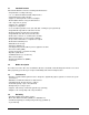
10.0 Seagate Technology support services Internet For information regarding Seagate products and services, visit www.seagate.com. Worldwide support is available 24 hours daily by email for your questions. Presales Support: Presales@Seagate.com Technical Support: DiscSupport@Seagate.com Warranty Support: http://www.seagate.com/www/en-us/support/warranty_&_returns_assistance mySeagate my.seagate.com is the industry's first Web portal designed specifically for OEMs and distributors.
Customer Service Operations Warranty Service Seagate offers worldwide customer support for Seagate products. Seagate distributors, OEMs and other direct customers should contact their Seagate Customer Service Operations (CSO) representative for warrantyrelated issues. Resellers or end users of drive products should contact their place of purchase or Seagate warranty service for assistance. Have your serial number and model or part number available.
Index Numerics 12 volt pins 52 5 volt pins 52 6 Gbps 62 A abort task set function 37 AC coupling 52 AC power requirements 19 ACA active status 47 ACA active, faulted initiator status 47 acoustics 27 active LED Out signal 52 actuator assembly design 5 adaptive caching 47 AFR 6 air cleanliness 27 air flow 35 illustrated 35 altitude 25 ambient 24 ANSI documents SCSI 4 Serial Attached SCSI 4 asynchronous event notification 47 audible noise 2 auto write and read reallocation programmable 6 automatic contingent
environmental limits 24 requirements 12 environmental control 27 error management 30 rates 12 errors 30 EU RoHS directive 28 requirements 37 intermediate/condition met/good status 47 intermediate/good status 47 internal data rate 8 internal defects/errors 30 internal drive characteristics 8 IRAW 33 F jumpers 34 FCC rules and regulations 2 features 6 interface 37 feed forward equalizer 62 FFE 62 firmware 6 corruption 42 flawed sector reallocation 6 Format command execution time 9 function complete, code
N office environment 27 operating 25, 26, 27 option selection 51 out-of-plane distortion 36 recovered media data 12 reference documents 4 relative humidity 25 reliability 6 specifications 12 reliability and service 13 repair and return information 18 reporting actual retry count 47 reservation conflict status 47 resonance 25 return information 18 RoHS 28 rotation speed 8 P S package size 26 package test specification 4 packaged 26 parameter rounding 47 PCBA 36 peak bits per inch 8 peak operating curren
allowable for non-flat surface 36 switches 34 synchronized spindle operation 47 system chassis 36 T task management functions 37 Abort task set 37 Clear ACA 37 Clear task set 37 terminate task 37 task management response codes 37 Function complete 00 37 Function not supported 05 37 Function reject 04 37 task set full status 47 technical support services 63 temperature 24, 35 limits 24 non-operating 24 regulation 2 See also cooling terminate task function 37 terminators 34 tracks per inch 8 transmitters 52
Seagate Technology LLC 920 Disc Drive, Scotts Valley, California 95066-4544, USA Publication Number: 100516228, Rev.