..................................... U4 Family .......................................... ST32112A, ST34311A .......................................... ST36421A, ST38421A .......................................... Ultra ATA Interface Drives ......................................... Product Manual .........................................
..................................... U4 Family .......................................... ST32112A, ST34311A ......................................... ST36421A, ST38421A .......................................... Ultra ATA Interface Drives ......................................... Product Manual .........................................
1999 Seagate Technology, Inc. All rights reserved Publication Number: SG35116-001, Rev. D, June 1999 Seagate, Seagate Technology, the Seagate logo and U4 are either trademarks or registered trademarks of Seagate Technology, Inc. Other product names are registered trademarks or trademarks of their owners. Seagate reserves the right to change, without notice, product offerings or specifications. No part of this publication may be reproduced in any form without written permission from Seagate Technology, Inc.
U4 Family Product Manual, Rev. D iii Contents Specification summary table . . . . . . . . . . . . . . . . . . . . . . . . . . . . . . 2 1.0 Drive specifications . . . . . . . . . . . . . . . . . . . . . . . . . . . . . . . . . 5 1.1 Formatted capacity . . . . . . . . . . . . . . . . . . . . . . . . . . . . . . . . . 5 1.1.1 Default logical geometry . . . . . . . . . . . . . . . . . . . . . . . . . 5 1.2 Physical organization . . . . . . . . . . . . . . . . . . . . . . . . . . . . . . . 5 1.
iv U4 Family Product Manual, Rev. D 2.0 Configuring and mounting the drive . . . . . . . . . . . . . . . . . . . 17 2.1 Handling and static-discharge precautions . . . . . . . . . . . . . . 17 2.2 Jumper settings . . . . . . . . . . . . . . . . . . . . . . . . . . . . . . . . . . 18 2.2.1 Master/slave configuration . . . . . . . . . . . . . . . . . . . . . . 18 2.2.2 Cable-select option . . . . . . . . . . . . . . . . . . . . . . . . . . . . 19 2.3 Ultra ATA/66 cable . . . . . . . . . . . . . . . . . . .
U4 Family Product Manual, Rev. D v Figures Figure 1. Typical startup and operation current profile . . . . . . . . . . . . 9 Figure 2. Master/slave jumper settings . . . . . . . . . . . . . . . . . . . . . . . 18 Figure 3. Mounting dimensions—top, side and end view . . . . . . . . . 20 Figure 4. I/O pins and supported ATA signals. . . . . . . . . . . . . . . . . .
vi U4 Family Product Manual, Rev. D.
U4 Family Product Manual, Rev. D 1 Introduction This manual describes the functional, mechanical and interface specifications for the U4 ST38421A, ST36421A, ST34311A and the ST32112A. These drives provide the following key features: • Low power consumption • Quiet operation • 10-5 msec seek time, 5-400-RPM and 256-Kbyte buffer for excellent desktop performance • High instantaneous (burst) data-transfer rates (up to 66.
2 U4 Family Product Manual, Rev. D Specification summary table The specifications listed in this table are for quick reference. For details on specification measurement or definition, see the appropriate section of this manual.
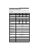
U4 Family Product Manual, Rev. D Drive Specification ST32112A 3 ST34311A ST36421A Track-to-track seek time (msec typical) 2.0 (read), 2.75 (write) Average seek time (msec typical) 10.5 (read), 11.5 (write) Full-stroke seek time (msec typical) 24.0 (read), 26.0 (write) Average latency (msec) 5.56 msec Power-on to ready (sec typical) 8 sec Standby to ready (sec typical) 7 sec Startup current (typical): 12V (peak) 1.5 amps Seek power (typical) 7.0 watts Idle mode (typical) 3.
4 Drive Specification Vibration, nonoperating Drive acoustics Sound power Idle mode Seek mode Nonrecoverable read errors Mean time between failures (power-on hours) Contact start-stop cycles (25°C, 40% relative humidity) Service life (years) U4 Family Product Manual, Rev. D ST32112A ST34311A ST36421A 5 Gs (0 to peak, 5–350 Hz) 3.3 (typical), 3.7(max) 3.9 (typical), 4.
U4 Family Product Manual, Rev. D 5 1.0 Drive specifications Unless otherwise noted, all specifications are measured under ambient conditions, at 25°C, and nominal power. For convenience, the phrases the drive and this drive are used throughout this manual to indicate the U4 ST38421A, ST36421A, ST34311A and the ST32112A. 1.
6 U4 Family Product Manual, Rev. D 1.3 Recording and interface technology Interface ATA Recording method 16/17 EPRML Recording density BPI (bits/inch) 241,000 Track density TPI (tracks/inch) 13,100 Areal density (Mbits/inch2 max) 3,179 Spindle speed (RPM) (± 0.2%) 5,400 Internal data-transfer rate (Mbits/sec max) 206 I/O data-transfer rate (Mbytes /sec max) 16.6 (PIO mode 4) 66.6 (Ultra DMA mode 4) Interleave 1:1 Cache buffer (Kbytes) 256 1.
U4 Family Product Manual, Rev. D 7 • Average seek time is a true statistical random average of at least 5,000 measurements of seeks between random tracks, less overhead. • Full-stroke seek time is one-half the time needed to seek from the first data cylinder to the maximum data cylinder and back to the first data cylinder. The full-stroke typical value is determined by averaging 100 full-stroke seeks in both directions. Typical seek times (msec) Read Write Track-to-track 2.0 2.75 Average 10.5 11.
8 U4 Family Product Manual, Rev. D • Seek Mode During seek mode, the read/write actuator arm moves toward a specific position on the disc surface and does not execute a read or write operation. Servo electronics are active. Seek mode power represents the worst-case power consumption, using only random seeks with read or write latency time. This mode is not typical and is provided for worst-case information.
U4 Family Product Manual, Rev. D 9 Typical Amps RMS Power Mode Typical Watts RMS 5V 12V — — 1.5 (peak) Seek (Random, no read/write) 7.0 0.39 0.42 Operating 5.7 0.34 0.33 Idle 3.1 0.24 0.16 Standby/Sleep 0.8 0.14 0.01 Spinup 1.7.1.1 Typical current profile Figure 1 shows a typical current profile. Current (amps) 1.2 1.0 0.8 0.6 0.4 0.2 0 1 2 3 4 5 Time (seconds) 6 Figure 1.
10 U4 Family Product Manual, Rev. D 1.7.2 Conducted noise Input noise ripple is measured at the host system power supply across an equivalent 80-ohm resistive load on the +12 volt line or an equivalent 15-ohm resistive load on the +5 volt line. • Using 12-volt power, the drive is expected to operate with a maximum of 120 mV peak-to-peak square-wave injected noise at up to 10 MHz.
U4 Family Product Manual, Rev. D 11 drive buffer is enabled, the heads are parked and the spindle is at rest. The drive accepts all commands and returns to Active mode any time disc access is necessary. • Sleep mode The drive enters Sleep mode after receiving a Sleep command from the host. In Sleep mode, the drive buffer is disabled, the heads are parked and the spindle is at rest. The drive leaves Sleep mode after it receives a Hard Reset or Soft Reset from the host.
12 U4 Family Product Manual, Rev. D 1.8.3.2 Wet bulb temperature Operating 29.4°C (84°F) max Nonoperating 40.0°C (104°F) max 1.8.4 Altitude Operating –61 m to 3,048 m (–200 ft to 10,000+ ft) Nonoperating –122 m to 12,192 m (–400 ft to 40,000+ ft) 1.8.5 Shock All shock specifications assume that the drive is mounted securely with the input shock applied at the drive mounting screws. Shock may be applied in the X, Y or Z axis. 1.8.5.
U4 Family Product Manual, Rev. D 13 1.8.6.1 Operating vibration The following table lists the maximum vibration levels that the drive may experience while meeting the performance standards specified in this document. 5–21 Hz 0.02-inch displacement (peak to peak) 22–350 Hz 0.5 Gs acceleration (zero to peak) 351–500 Hz 0.3 Gs acceleration (zero to peak) 1.8.6.
14 U4 Family Product Manual, Rev. D 1.10 Electromagnetic susceptibility The drive operates without errors when subjected to the following: Radiated noise ≤ 3 volt/meter, 30 Hz to 500 MHz Electrostatic discharge* ≤ 10 KVolts Magnetic field strength ≤ 5 Gauss * Electrostatic discharge susceptibility is measured with the drive mounted in a representative computer system (mounted to a ground plane with an earth ground). Discharges are applied to the bezel or other external surfaces on the ground plane.
U4 Family Product Manual, Rev. D 15 comply with the directives when used in the test systems, we cannot guarantee that all systems will comply with the directives. The drive is designed for operation inside a properly designed enclosure, with properly shielded I/O cable (if necessary) and terminators on all unused I/O ports. Computer manufacturers and system integrators should confirm EMC compliance and provide CE marking for their products.
16 U4 Family Product Manual, Rev. D If necessary, you should consult your dealer or an experienced radio/ television technician for additional suggestions. You may find helpful the following booklet prepared by the Federal Communications Commission: How to Identify and Resolve Radio-Television Interference Problems. This booklet is available from the Superintendent of Documents, U.S. Government Printing Office, Washington, DC 20402. Refer to publication number 004-000-00345-4.
U4 Family Product Manual, Rev. D 17 2.0 Configuring and mounting the drive This section contains the specifications and instructions for configuring and mounting the drive. 2.1 Handling and static-discharge precautions After unpacking, and before installation, the drive may be exposed to potential handling and electrostatic discharge (ESD) hazards.
18 U4 Family Product Manual, Rev. D 2.2 Jumper settings 2.2.1 Master/slave configuration The options jumper block (J8) shown in Figure 2 is used to configure the drive for operation. It is the 6-pin dual header between the I/O connector and the power connector. Use the following settings to configure the drive as a master or a slave. Master or single drive. The drive is configured at the factory for a master or single-drive operation with a jumper set on pins 7 and 8. Drive is slave.
U4 Family Product Manual, Rev. D 19 2.2.2 Cable-select option Computers that use cable-select determine the master and slave drives by selecting or deselecting pin 28, CSEL, on the interface bus. Master and slave drives are determined by their physical position on the cable. To enable cable select, set a jumper on pins 5 and 6 as shown in Figure 2 on page 18. Consult your computer manual to determine whether your computer supports this option. 2.
20 U4 Family Product Manual, Rev. D Note: Dimensions are shown in inches (mm). 0.180 ± 0.015 (4.57 ± 0.38) 1.00 ± 0.028 (25.4 ± 0.7) 0.230 ± 0.015 (5.84 ± 0.38) 2.23 ± 0.03 (56.6 ± 0.8) 3X 6-32 UNC-2B max. insertion depth 0.14 (3.6) both sides 3.72 ± 0.03 (94.5 ± 0.8) 4X 6-32 UNC-2B max. insertion depth 0.22 (5.6) 4.000 ± 0.010 (101.60 ± 0.25) 1.750 ± 0.010 (44.45 ± 0.25) 5.75 ± 0.03 (146.1 ± 0.8) 2.362 ± 0.010 (59.99 ± 0.25) 2.375 +0.030, –0.005 (60.33 +0.76, –0.13) 0.630 +0.030, –0.005 (16.
U4 Family Product Manual, Rev. D 21 3.0 ATA interface These drives use the industry-standard ATA task file interface that supports 16-bit data transfers. It supports ATA programmed input/output (PIO) modes 0–4; multiword DMA modes 0–2, and Ultra DMA modes 0–4. The drive also supports the use of the IORDY signal to provide reliable high-speed data transfers. You can use a daisy-chain cable to connect two drives to a single AT host bus.
22 U4 Family Product Manual, Rev.
U4 Family Product Manual, Rev. D 23 3.2 ATA Interface commands 3.2.1 Supported ATA commands The following table lists ATA-standard commands that the drive supports. For a detailed description of the ATA commands, refer to the Draft ATA-4 Standard. See Section 3.2.4 on page 30 for details and subcommands used in the S.M.A.R.T. implementation.
24 U4 Family Product Manual, Rev. D Command name Write Sectors Command code (in hex) 30H, 31H ATA-standard power-management commands Check Power Mode 98H or E5H Idle 97H or E3H Idle Immediate 95H or E1H Sleep 99H or E6H Standby 96H or E2H Standby Immediate 94H or E0H ATA-standard security commands Security Set Password F1H Security Unlock F2H Security Erase Prepare F3H Security Erase Unit F4H Security Freeze Lock F5H Security Disable Password F6H 3.2.
U4 Family Product Manual, Rev.
26 U4 Family Product Manual, Rev.
U4 Family Product Manual, Rev.
28 U4 Family Product Manual, Rev. D Word 91–92 Description Value ATA-reserved 0000H Hardware Reset Value (see description following this table) 4000H 94–127 ATA-reserved 0000H 128 Security Status 0001H 129–159 Seagate-reserved xxxxH 160–255 ATA-reserved 0000H 93 Note. See the bit descriptions below for words, 63, 88, and 93 of the Identify Drive data: Description (if bit is set to 1) Bit Word 63 0 Multiword DMA mode 0 is supported. 1 Multiword DMA mode 1 is supported.
U4 Family Product Manual, Rev. D 11 Ultra DMA mode 3 is currently active. 12 Ultra DMA mode 4 is currently active. Bit Word 93 13 1=80-conductor cable detected, CBLID above VIH 0=40-conductor cable detected, CBLID below VIL 29 3.2.3 Set Features command This command controls the implementation of various features that the drive supports. When the drive receives this command, it sets BSY, checks the contents of the Features register, clears BSY and generates an interrupt.
30 U4 Family Product Manual, Rev. D 55H Disable read look-ahead (read cache) feature. 82H Disable write cache. AAH Enable read look-ahead (read cache) feature (default). Note. At power-on, or after a hardware or software reset, the default values of the features are as indicated above. 3.2.4 S.M.A.R.T. commands S.M.A.R.T. provides near-term failure prediction for disc drives. When S.M.A.R.T. is enabled, the drive monitors predetermined drive attributes that are susceptible to degradation over time.
U4 Family Product Manual, Rev.
32 U4 Family Product Manual, Rev.
U4 Family Product Manual, Rev.
34 U4 Family Product Manual, Rev. D Seagate Technology, Inc. 920 Disc Drive, Scotts Valley, California 95066, USA Publication Number: SG35116-001, Rev.