Product Manual Constellation ES Series SAS ® Standard Models Self-Encrypting Drive Models ST32000444SS ST32000445SS ST31000424SS ST31000425SS ST3500414SS ST3500415SS 100602414 Rev.
Revision history Revision Rev. A Rev. B Rev. C Rev. D Date 12/02/09 01/19/10 02/22/10 03/15/10 Sheets affected or comments Initial release. 9 & 10. 36. 9. © 2010, Seagate Technology LLC All rights reserved. Publication number: 100602414, Rev. D March 2010 Seagate, Seagate Technology and the Wave logo are registered trademarks of Seagate Technology LLC in the United States and/or other countries.
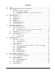
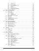
Contents 1.0 Scope. . . . . . . . . . . . . . . . . . . . . . . . . . . . . . . . . . . . . . . . . . . . . . . . . . . . . . . . . . . . . . . . . . . . . . . . 1 2.0 Applicable standards and reference documentation . . . . . . . . . . . . . . . . . . . . . . . . . . . . . . . . . 2.1 Standards . . . . . . . . . . . . . . . . . . . . . . . . . . . . . . . . . . . . . . . . . . . . . . . . . . . . . . . . . . . . . . 2.1.1 Electromagnetic compatibility. . . . . . . . . . . . . . . . . . . . . . . . . . .
6.5.1 Temperature . . . . . . . . . . . . . . . . . . . . . . . . . . . . . . . . . . . . . . . . . . . . . . . . . . . . 6.5.2 Relative humidity . . . . . . . . . . . . . . . . . . . . . . . . . . . . . . . . . . . . . . . . . . . . . . . . 6.5.3 Effective altitude (sea level) . . . . . . . . . . . . . . . . . . . . . . . . . . . . . . . . . . . . . . . . 6.5.4 Shock and vibration . . . . . . . . . . . . . . . . . . . . . . . . . . . . . . . . . . . . . . . . . . . . . . 6.5.5 Acoustics . . . . . . . . . .
10.6 10.7 11.0 10.5.2 Differential signals . . . . . . . . . . . . . . . . . . . . . . . . . . . . . . . . . . . . . . . . . . . . . . . 68 SAS-2 Specification Compliance . . . . . . . . . . . . . . . . . . . . . . . . . . . . . . . . . . . . . . . . . . . . 68 Additional information . . . . . . . . . . . . . . . . . . . . . . . . . . . . . . . . . . . . . . . . . . . . . . . . . . . . 68 Seagate Technology support services . . . . . . . . . . . . . . . . . . . . . . . . . . . . . . . . . . . . . . . . .
iv ConstellationES Series SAS Product Manual, Rev.
List of Figures Figure 1. ST32000444SS & ST32000445SS model current profiles 26 Figure 2. ST31000424SS & ST31000425SS model current profiles . . . . . . . . . . . . . . . . . . . . . . . . . . . . . . . . . . . . . . .27 Figure 3. ST3500414SS & ST3500415SS model current profiles . . . . . . . . . . . . . . . . . . . . . . . . . . . . . . . . . . . . . . . . .28 Figure 4. ST32000444SS & ST32000445SS (3Gb) DC current and power vs. input/output operations per second. . .29 Figure 5.
vi ConstellationES Series SAS Product Manual, Rev.
1.0 Scope This manual describes Seagate Technology® LLC, Constellation® ES Series SAS (Serial Attached SCSI) disc drives. Constellation ES drives support the SAS Protocol specifications to the extent described in this manual. The SAS Interface Manual (part number 100293071) describes the general SAS characteristics of this and other Seagate SAS drives.
2.0 Applicable standards and reference documentation The drives documented in this manual have been developed as system peripherals to the highest standards of design and construction. The drives depends on host equipment to provide adequate power and environment for optimum performance and compliance with applicable industry and governmental regulations. Special attention must be given in the areas of safety, power distribution, shielding, audible noise control, and temperature regulation.
2.1.2 Electromagnetic compliance Seagate uses an independent laboratory to confirm compliance with the directives/standards for CE Marking and C-Tick Marking. The drive was tested in a representative system for typical applications. The selected system represents the most popular characteristics for test platforms.
2.1.3 European Union Restriction of Hazardous Substances (RoHS) The European Union Restriction of Hazardous Substances (RoHS) Directive, restricts the presence of chemical substances, including Lead, Cadmium, Mercury, Hexavalent Chromium, PBB and PBDE, in electronic products, effective July 2006. This drive is manufactured with components and materials that comply with the RoHS Directive. A number of parts and materials in Seagate products are procured from external suppliers.
3.0 General description Constellation ES drives provide high performance, high capacity data storage for a variety of systems including engineering workstations, network servers, mainframes, and supercomputers. The Serial Attached SCSI interface is designed to meet next-generation computing demands for performance, scalability, flexibility and highdensity storage requirements.
3.1 Standard features Constellation ES drives have the following standard features: • • • • • • • • • • • • • • • • • • • • • • • • • Perpendicular recording technology 1.5 / 3 / 6 Gb Serial Attached SCSI (SAS) interface Integrated dual port SAS controller supporting the SCSI protocol Support for SAS expanders and fanout adapters Firmware downloadable using the SAS interface 128 - deep task set (queue) Supports up to 32 initiators Jumperless configuration.
3.3 • • • • • • Programmable multi-segmentable cache buffer 600MB/s maximum instantaneous data transfers. 7200 RPM spindle. Average latency = 4.16ms Background processing of queue Supports start and stop commands (spindle stops spinning) Adaptive seek velocity; improved seek performance Note. 3.4 • • • • • Performance There is no significant performance difference between Self-Encrypting Drive and standard (nonSelf-Encrypting Drive) models. Reliability Annualized Failure Rate (AFR) of 0.
3.7 Factory-installed options You may order the following items which are incorporated at the manufacturing facility during production or packaged before shipping. Some of the options available are (not an exhaustive list of possible options): • Other capacities can be ordered depending on sparing scheme and sector size requested. • Single-unit shipping pack. The drive is normally shipped in bulk packaging to provide maximum protection against transit damage.
4.0 Performance characteristics This section provides detailed information concerning performance-related characteristics and features of Constellation ES drives. 4.1 Internal drive characteristics ST32000444SS ST32000445SS 2000 8 1,012,608 250,000 248,600 237,000 1,515,000 347 95 - 212 7200 4.
4.2.2 Format command execution time for 512-byte sectors (minutes) ST32000444SS ST32000445SS ST31000424SS ST31000425SS ST3500414SS ST3500415SS Maximum (with verify) 627 345 173 Maximum (without verify) 314 173 86 Note. 4.2.3 There is approximately a 1.5 increase in time to format a SED drive versus a non-SED drive of the same capacity.
4.4 Prefetch/multi-segmented cache control The drive provides a prefetch (read look-ahead) and multi-segmented cache control algorithms that in many cases can enhance system performance. Cache refers to the drive buffer storage space when it is used in cache operations. To select this feature, the host sends the Mode Select command with the proper values in the applicable bytes in page 08h.
4.5.1 Caching write data Write caching is a write operation by the drive that makes use of a drive buffer storage area where the data to be written to the medium is stored while the drive performs the Write command. If read caching is enabled (RCD=0), then data written to the medium is retained in the cache to be made available for future read cache hits. The same buffer space and segmentation is used as set up for read functions.
5.0 Reliability specifications The following reliability specifications assume correct host and drive operational interface, including all interface timings, power supply voltages, environmental requirements and drive mounting constraints. Seek error rate: Read Error Rates1 Recovered Data Unrecovered Data Miscorrected Data Interface error rate: Mean Time Between Failure (MTBF): Annualized Failure Rate (AFR): Preventive maintenance: 1.
5.1.3 Seek errors A seek error is defined as a failure of the drive to position the heads to the addressed track. After detecting an initial seek error, the drive automatically performs an error recovery process. If the error recovery process fails, a seek positioning error (Error code = 15h or 02h) will be reported with a Hardware error (04h) in the Sense Key. Recoverable seek errors are specified at Less than 10 errors in 108 seeks.
Caution. 5.2.4 The drive motor must come to a complete stop prior to changing the plane of operation. This time is required to insure data integrity. S.M.A.R.T. S.M.A.R.T. is an acronym for Self-Monitoring Analysis and Reporting Technology. This technology is intended to recognize conditions that indicate imminent drive failure and is designed to provide sufficient warning of a failure to allow you to back up the data before an actual failure occurs. Note.
S.M.A.R.T. measures error rates. All errors for each monitored attribute are recorded. A counter keeps track of the number of errors for the current interval. This counter is referred to as the Failure Counter. Error rate is the number of errors per operation. The algorithm that S.M.A.R.T. uses to record rates of error is to set thresholds for the number of errors and their interval. If the number of errors exceeds the threshold before the interval expires, the error rate is considered to be unacceptable.
5.2.6 Drive Self Test (DST) Drive Self Test (DST) is a technology designed to recognize drive fault conditions that qualify the drive as a failed unit. DST validates the functionality of the drive at a system level. There are two test coverage options implemented in DST: 1. Extended test 2. Short test The most thorough option is the extended test that performs various tests on the drive and scans every logical block address (LBA) of the drive.
5.2.6.2.3 Short and extended tests DST has two testing options: 1. short 2. extended These testing options are described in the following two subsections. Each test consists of three segments: an electrical test segment, a servo test segment, and a read/verify scan segment. Short test (Function Code: 001b) The purpose of the short test is to provide a time-limited test that tests as much of the drive as possible within 120 seconds.
5.2.
6.0 Physical/electrical specifications This section provides information relating to the physical and electrical characteristics of the drive. 6.1 PowerChoiceTM power management Drives using the load/unload architecture provide programmable power management to tailor systems for performance and greater energy efficiency. The table below lists the supported PowerChoice modes. The further you go down in the table, the more power savings you get.
6.1.1 PowerChoice reporting methods PowerChoiceTM provides these reporting methods for tracking purposes: Request Sense command reports • Current power condition • Method of entry Note. Processing the Request Sense command does not impact the drive’s power save state.
Table 2: 2000GB drive (Standard & SED model) DC power requirements Notes Voltage 3.0Gb mode 6.0Gb mode (Amps) (Amps) (Amps) (Amps) +5V +12V [4] +5V +12V [4] Regulation [5] ±5% ±5% [2] ±5% ±5% [2] Avg idle current DCX [1] [7] 0.41 0.43 0.42 0.43 Idle_A 0.40 0.43 0.42 0.43 Idle_B 0.22 0.37 0.23 0.37 Idle_C/ Standby_Y 0.22 0.21 0.23 0.21 Standby_Z 0.22 0.02 0.23 0.02 Advanced idle current Maximum starting current (peak DC) DC 3σ [5] 0.66 2.08 0.67 2.
Table 3: 1000GB drive (Standard & SED model) DC power requirements Notes Voltage 3.0Gb mode 6.0Gb mode (Amps) (Amps) (Amps) (Amps) +5V +12V [4] +5V +12V [4] Regulation [5] ±5% ±5% [2] ±5% ±5% [2] Avg idle current DCX [1] [7] 0.39 0.28 0.41 0.28 Idle_A 0.37 0.28 0.41 0.28 Idle_B 0.21 0.24 0.22 0.24 Idle_C/ Standby_Y 0.21 0.15 0.22 0.15 Standby_Z 0.21 0.02 0.22 0.02 Advanced idle current Maximum starting current (peak DC) DC 3σ [5] 0.56 1.89 0.58 1.
Table 4: 500GB drive (Standard & SED model) DC power requirements Notes Voltage 3.0Gb mode 6.0Gb mode (Amps) (Amps) (Amps) (Amps) +5V +12V [4] +5V +12V [4] Regulation [5] ±5% ±5% [2] ±5% ±5% [2] Avg idle current DCX [1] [7] 0.42 0.21 0.43 0.21 Idle_A 0.41 0.21 0.43 0.21 Idle_B 0.23 0.19 0.24 0.19 Idle_C/ Standby_Y 0.23 0.12 0.24 0.12 Standby_Z 0.22 0.02 0.24 0.02 Advanced idle current Maximum starting current (peak DC) DC 3σ [5] 0.55 1.88 0.56 1.
[5] [6] [7] [8] [9] See +12V current profile in Figure 3. This condition occurs after OOB and Speed Negotiation completes but before the drive has received the Notify Spinup primitive. See paragraph 6.3.1, "Conducted noise immunity." Specified voltage tolerance includes ripple, noise, and transient response. Operating condition is defined as random 8 block reads. During idle, the drive heads are relocated every 60 seconds to a random location within the band from three-quarters to maximum track.
6.3.3 Current profiles The +12V (top) and +5V (bottom) current profiles for the Constellation ES drives are shown below. Figure 1. ST32000444SS & ST32000445SS model current profiles Note: All times and currents are typical. See Table 2 for maximum current requirements. 26 ConstellationES Series SAS Product Manual, Rev.
Figure 2. ST31000424SS & ST31000425SS model current profiles Note: All times and currents are typical. See Table 2 for maximum current requirements. ConstellationES Series SAS Product Manual, Rev.
Figure 3. ST3500414SS & ST3500415SS model current profiles Note: All times and currents are typical. See Table 2 for maximum current requirements. 28 ConstellationES Series SAS Product Manual, Rev.
6.4 Power dissipation ST32000444SS and ST32000445SS in 3Gb operation Please refer to Table 2 for power dissipation numbers. To obtain operating power for typical random read operations, refer to the following I/O rate curve (see Figure 8). Locate the typical I/O rate for a drive in your system on the horizontal axis and read the corresponding +5 volt current, +12 volt current, and total watts on the vertical axis. To calculate BTUs per hour, multiply watts by 3.4123.
ST32000444SS and ST32000445SS in 6Gb operation Please refer to Table 2 for power dissipation numbers. To obtain operating power for typical random read operations, refer to the following I/O rate curve (see Figure 9.). Locate the typical I/O rate for a drive in your system on the horizontal axis and read the corresponding +5 volt current, +12 volt current, and total watts on the vertical axis. To calculate BTUs per hour, multiply watts by 3.4123. Figure 5.
ST31000424SS and ST31000425SS in 3Gb operation Please refer to Table 2 for power dissipation numbers. To obtain operating power for typical random read operations, refer to the following I/O rate curve (see Figure 8). Locate the typical I/O rate for a drive in your system on the horizontal axis and read the corresponding +5 volt current, +12 volt current, and total watts on the vertical axis. To calculate BTUs per hour, multiply watts by 3.4123. ST31000424SS CURRENT/POWER vs THROUGHPUT (SAS - 3.
ST31000424SS and ST31000425SS in 6Gb operation Please refer to Table 2 for power dissipation numbers. To obtain operating power for typical random read operations, refer to the following I/O rate curve (see Figure 9.). Locate the typical I/O rate for a drive in your system on the horizontal axis and read the corresponding +5 volt current, +12 volt current, and total watts on the vertical axis. To calculate BTUs per hour, multiply watts by 3.4123. Figure 7.
ST3500414SS and ST3500415SS in 3Gb operation Please refer to Table 2 for power dissipation numbers. To obtain operating power for typical random read operations, refer to the following I/O rate curve (see Figure 8). Locate the typical I/O rate for a drive in your system on the horizontal axis and read the corresponding +5 volt current, +12 volt current, and total watts on the vertical axis. To calculate BTUs per hour, multiply watts by 3.4123. ST3500414SS CURRENT/POWER vs THROUGHPUT (SAS - 3.
ST3500414SS and ST3500415SS in 6Gb operation Please refer to Table 2 for power dissipation numbers. To obtain operating power for typical random read operations, refer to the following I/O rate curve (see Figure 9.). Locate the typical I/O rate for a drive in your system on the horizontal axis and read the corresponding +5 volt current, +12 volt current, and total watts on the vertical axis. To calculate BTUs per hour, multiply watts by 3.4123. Figure 9.
6.5 Environmental limits Temperature and humidity values experienced by the drive must be such that condensation does not occur on any drive part. Altitude and atmospheric pressure specifications are referenced to a standard day at 58.7°F (14.8°C). Maximum wet bulb temperature is 82°F (28°C). 6.5.1 Temperature a. Operating To obtain optimal performance, drives should be run at nominal case temperatures.
6.5.3 Effective altitude (sea level) a. Operating –200 to +10,000 feet (–61 to +3,048 meters) b. Non-operating –200 to +40,000 feet (–61 to +12,210 meters) 6.5.4 Shock and vibration Shock and vibration limits specified in this document are measured directly on the drive chassis. If the drive is installed in an enclosure to which the stated shock and/or vibration criteria is applied, resonances may occur internally to the enclosure resulting in drive movement in excess of the stated limits.
d. Packaged Disc drives shipped as loose load (not palletized) general freight will be packaged to withstand drops from heights as defined in the table below. For additional details refer to Seagate specifications 30190-001 (under 100 lbs/45 kg) or 30191-001 (over 100 lbs/45 Kg). Package size Packaged/product weight Drop height <600 cu in (<9,800 cu cm) 600-1800 cu in (9,800-19,700 cu cm) >1800 cu in (>19,700 cu cm) >600 cu in (>9,800 cu cm) Any 0-20 lb (0 to 9.1 kg) 0-20 lb (0 to 9.1 kg) 20-40 lb (9.
6.5.4.2 Vibration a. Operating—normal The drive as installed for normal operation, shall comply with the complete specified performance while subjected to continuous vibration not exceeding 5 - 22 Hz 22 - 350 Hz 350 - 500 Hz 0.25 Gs, limited displacement 0.5 Gs 0.25 Gs Vibration may be applied in the X, Y, or Z axis. b.
should never be exposed to condensing water on the surface of the printed circuit board assembly (PCBA) or exposed to an ambient relative humidity greater than 95%. Materials used in cabinet fabrication, such as vulcanized rubber, that can outgas corrosive compounds should be minimized or eliminated. The useful life of any electronic equipment may be extended by replacing materials near circuitry with sulfide-free alternatives. 6.5.8 Electromagnetic susceptibility See Section 2.1.1.1.
6.6 Mechanical specifications The following nominal dimensions are exclusive of the decorative front panel accessory. However, dimensions of the front panel are shown in figure below. Refer to Figure 12 for detailed mounting configuration dimensions. See Section 9.3, “Drive mounting.” Height: Width: Depth: Weight: .5TB models 1TB models 2TB models Figure 12. 40 1.008 in (± 0.008) 4.000 in (± 0.008) 5.755 in (± 0.005) 25.6 mm (± 0.20) 101.6 mm (± 0.20) 146.18 mm (±0.13) 1.34 lb 1.41 lb 1.
7.0 About self-encrypting drives Self-encrypting drives (SEDs) offer encryption and security services for the protection of stored data, commonly known as “protection of data at rest.” These drives are compliant with the Trusted Computing Group (TCG) Enterprise Storage Specifications as detailed in Section 2.2. The Trusted Computing Group (TCG) is an organization sponsored and operated by companies in the computer, storage and digital communications industry.
7.2.2 Locking SP The Locking SP controls read/write access to the media and the cryptographic erase feature. Access to the Locking SP is available using the BandMasterX or EraseMaster passwords. Since the drive owner can define up to 16 data bands on the drive, each data band has its own password called BandMasterX where X is the number of the data band (0 through 15). 7.2.3 Default password When the drive is shipped from the factory, all passwords are set to the value of MSID.
7.6 Cryptographic erase A significant feature of SEDs is the ability to perform a cryptographic erase. This involves the host telling the drive to change the data encryption key for a particular band. Once changed, the data is no longer recoverable since it was written with one key and will be read using a different key. Since the drive overwrites the old key with the new one, and keeps no history of key changes, the user data can never be recovered.
8.0 Defect and error management Seagate continues to use innovative technologies to manage defects and errors. These technologies are designed to increase data integrity, perform drive self-maintenance, and validate proper drive operation. SCSI defect and error management involves drive internal defect/error management and SAS system error considerations (errors in communications between the initiator and the drive).
The drive firmware error recovery algorithms consist of 12 levels for read recoveries and five levels for write. Each level may consist of multiple steps, where a step is defined as a recovery function involving a single reread or re-write attempt. The maximum level used by the drive in LBA recovery is determined by the read and write retry counts. Table 5 equates the read and write retry count with the maximum possible recovery time for read and write recovery of individual LBAs.
8.4 Background Media Scan Background Media Scan (BMS) is a self-initiated media scan. BMS is defined in the T10 document SPC-4 available from the T10 committee. BMS performs sequential reads across the entire pack of the media while the drive is idle. In RAID arrays, BMS allows hot spare drives to be scanned for defects prior to being put into service by the host system. On regular duty drives, if the host system makes use of the BMS Log Page, it can avoid placing data in suspect locations on the media.
8.7 Idle Read After Write Idle Read After Write (IRAW) utilizes idle time to verify the integrity of recently written data. During idle periods, no active system requests, the drive reads recently written data from the media and compares it to valid write command data resident in the drives data buffer. Any sectors that fail the comparison result in the invocation of a rewrite and auto-reallocation process. The process attempts to rewrite the data to the original location.
9.0 Installation Constellation ES disc drive installation is a plug-and-play process. There are no jumpers, switches, or terminators on the drive. SAS drives are designed to be used in a host system that provides a SAS-compatible backplane with bays designed to accommodate the drive. In such systems, the host system typically provides a carrier or tray into which you need to mount the drive. Mount the drive to the carrier or tray provided by the host system using four M3 x 0.5 metric screws.
9.2 Cooling Cabinet cooling must be designed by the customer so that the ambient temperature immediately surrounding the drive will not exceed temperature conditions specified in Section 6.5.1, "Temperature." The rack, cabinet, or drawer environment for the drive must provide heat removal from the electronics and head and disc assembly (HDA). You should confirm that adequate heat removal is provided using the temperature measurement guidelines described in Section 6.5.1.
9.3 Drive mounting Mount the drive using the bottom or side mounting holes. If you mount the drive using the bottom holes, ensure that you do not physically distort the drive by attempting to mount it on a stiff, non-flat surface. The allowable mounting surface stiffness is 80 lb/in (14.0 N/mm).
10.0 Interface requirements This section partially describes the interface requirements as implemented on Constellation ES drives. Additional information is provided in the SAS Interface Manual (part number 100293071). 10.1 SAS features This section lists the SAS-specific features supported by Constellation ES drives. 10.1.1 task management functions Table 6 lists the SAS task management functions supported.
10.2 Dual port support Constellation ES SAS drives have two independent ports. These ports may be connected in the same or different SCSI domains. Each drive port has a unique SAS address. The two ports have the capability of independent port clocking (e.g. both ports can run at 6Gb/s or the first port can run at 6Gb/s while the second port runs at 3Gb/s. The supported link rates are 1.5, 3.0, or 6.0 Gb/s.
10.3 SCSI commands supported Table 8 lists the SCSI commands supported by Constellation ES drives.
Table 8: Supported commands Command name Command code Supported Last n Deferred Errors or Asynchronous Events page (0Bh) N Last n Error Events page (07h) N Non-medium Error page (06h) Y Pages Supported list (00h) Y Read Error Counter page (03h) Y Read Reverse Error Counter page (04h) N Self-test Results page (10h) Y Start-stop Cycle Counter page (0Eh) Y Temperature page (0Dh) Y Verify Error Counter page (05h) Y Write error counter page (02h) Y Mode Select (same pages as Mode Sense
Table 8: Supported commands Command name Command code Supported Read Capacity (10) 25h Y Read Capacity (16) 9Eh/10h N Read Defect Data (10) 37h Y Read Defect Data (12) B7h Y Read Long 3Eh Y (non-SED drives only) Read Long (16) 9Eh/11h N Reassign Blocks 07h Y Receive Diagnostic Results 1Ch Y Supported Diagnostics pages (00h) Y Translate page (40h) Y Release 17h Y Release (10) 57h Y Report LUNs A0h Y Request Sense 03h Y Actual Retry Count bytes Y Extended Sense
Table 8: Supported commands Command name Command code Supported Verify (10) 2Fh Y BYTCHK bit Y Verify (12) AFh N Verify (16) AFh N Verify (32) 7Fh/000Ah N Write (6) 0Ah Y Write (10) 2Ah Y DPO bit Y FUA bit Y Write (12) AAh N Write (16) 8Ah N Write (32) 7Fh/000Bh N Write and Verify (10) 2Eh Y DPO bit Y Write and Verify (12) AEh N Write and Verify (16) 8Eh N Write and Verify (32) 7Fh/000Ch N Write Buffer (modes 0, 2, supported) 3Bh Y (non-SED drives only)
10.3.1 Inquiry data Table 9 lists the Inquiry command data that the drive should return to the initiator per the format given in the SAS Interface Manual.
When power is applied to the drive, it takes saved values from the media and stores them as current values in volatile memory. It is not possible to change the current values (or the saved values) with a Mode Select command before the drive achieves operating speed and is “ready.” An attempt to do so results in a “Check Condition” status. On drives requiring unique saved values, the required unique saved values are stored into the saved values storage location on the media prior to shipping the drive.
Table 10: Mode Sense data changeable and default values for ST32000444SS/ST32000445SS drives MODE DATA HEADER: 01 92 00 10 00 00 00 08 BLOCK DESCRIPTOR: e8 e0 88 b0 00 00 02 00 MODE PAGES: DEF 81 0a c0 0b ff 00 00 00 05 00 ff ff CHG 81 0a ff ff 00 00 00 00 ff 00 ff ff DEF CHG 82 0e 00 00 00 00 00 00 00 00 01 3a 00 00 00 00 82 0e 00 00 00 00 00 00 00 00 ff ff 00 00 00 00 DEF CHG 83 16 bb d0 00 00 00 00 03 80 04 c4 02 00 00 01 00 9c 00 26 40 00 00 00 83 16 00 00 00 00 00 00 00 00 00 00 00 00 00 00 00 00
Table 11: Mode Sense data changeable and default values for ST31000424SS/ST31000425SS drives MODE DATA HEADER: 01 92 00 10 00 00 00 08 BLOCK DESCRIPTOR: 74 70 6d b0 00 00 02 00 MODE PAGES: DEF 81 0a c0 0b ff 00 00 00 05 00 ff ff CHG 81 0a ff ff 00 00 00 00 ff 00 ff ff DEF CHG 82 0e 00 00 00 00 00 00 00 00 01 3a 00 00 00 00 82 0e 00 00 00 00 00 00 00 00 ff ff 00 00 00 00 DEF CHG 83 16 bb d0 00 00 00 00 03 80 04 c4 02 00 00 01 00 7e 00 26 40 00 00 00 83 16 00 00 00 00 00 00 00 00 00 00 00 00 00 00 00 00
Table 12: Mode Sense data changeable and default values for ST3500414SS/ST3500415SS drives MODE DATA HEADER: 01 92 00 10 00 00 00 08 BLOCK DESCRIPTOR: 3a 38 60 30 00 00 02 00 MODE PAGES: DEF 81 0a c0 0b ff 00 00 00 05 00 ff ff CHG 81 0a ff ff 00 00 00 00 ff 00 ff ff DEF CHG 82 0e 00 00 00 00 00 00 00 00 01 3a 00 00 00 00 82 0e 00 00 00 00 00 00 00 00 ff ff 00 00 00 00 DEF CHG 83 16 bb d0 00 00 00 00 03 80 04 c4 02 00 00 01 00 7e 00 26 40 00 00 00 83 16 00 00 00 00 00 00 00 00 00 00 00 00 00 00 00 00 00
10.4 Miscellaneous operating features and conditions Table 13 lists various features and conditions. A “Y” in the support column indicates the feature or condition is supported. An “N” in the support column indicates the feature or condition is not supported.
10.4.1 SAS physical interface Figure 15 shows the location of the SAS device connector J1. Figures 16 and 17 provide the dimensions of the SAS connector. Details of the physical, electrical, and logical characteristics are provided within this section. The operational aspects of Seagate’s SAS drives are provided in the SAS Interface Manual. Figure 15. Physical interface ConstellationES Series SAS Product Manual, Rev.
0.80 (6X) 5.92 7.62 4.65 0.52 2.00 (3X) 0.45 5.08 0.08 x 45 0.03 (7X) 0.10 M E 42.73 REF. 41.13 0.30 0.15 0.20 B 0.05 (2X) C A B 4.00 1.10 0.08 0.15 D 0.30 CL OF DATUM D 0.05 (4X) A B R0.30 C 0.08 (4X) SEE Detail1 33.43 0.05 B 15.875 15.875 1.27 (14X) 1.27 (6X) 0.84 5.08 0.05 (22X) 0.15 B 4.90 0.08 0.35MIN P15 P1 S7 S1 CL OF DATUM B Figure 16. 64 SAS device plug dimensions ConstellationES Series SAS Product Manual, Rev.
Detail A 6.10 S14 2.25 S8 0.05 x 45 (5X) 0.05 0.40 4.85 0.30 0.05 0.10 B 0.05 X 45 (3X) CORING ALLOWED IN THIS AREA. E 4.40 0.15 R0.30 0.08 SEE Detail 2 C 1.95 0.08 A 45 0.35 3.90 0.05 0.15 SECTION C - C SECTION A - A 0.08 0.05 CONTACT SURFACE FLUSH TO DATUM A 0.03 65 1.23 0.08 0.05 0.05 1.90 0.08 30 Detail 2 2.40 0.08 0.10 A SECTION B - B D Figure 17. SAS device plug dimensions (detail) ConstellationES Series SAS Product Manual, Rev.
10.4.2 Physical characteristics This section defines physical interface connector. 10.4.3 Connector requirements Contact your preferred connector manufacturer for mating part information. Part numbers for SAS connectors will be provided in a future revision of this publication when production parts are available from major connector manufacturers. The SAS device connector is illustrated in Figures 16 and 17. 10.4.
10.4.6 SAS transmitters and receivers A typical SAS differential copper transmitter and receiver pair is shown in Figure 18. The receiver is AC coupling to eliminate ground shift noise. .01 TX Differential Transfer Medium Transmitter 100 TY Figure 18. SAS transmitters and receivers 10.4.7 Power RX Receiver 100 .01 RY The drive receives power (+5 volts and +12 volts) through the SAS device connector. Three +12 volt pins provide power to the drive, 2 short and 1 long.
The Ready LED Out signal is designed to pull down the cathode of an LED. The anode is attached to the proper +3.3 volt supply through an appropriate current limiting resistor. The LED and the current limiting resistor are external to the drive. See Table 17 for the output characteristics of the LED drive signals. Table 17: LED drive signal State Test condition Output voltage LED off, high 0 V ≤VOH ≤3.6 V -100 µA < IOH < 100 µA LED on, low IOL = 15 mA 0 ≤VOL ≤0.225 V 10.5.
11.0 Seagate Technology support services Web For information regarding Seagate products and services, visit www.seagate.com. Worldwide support is available 24 hours daily by email for your questions. Presales Support: Presales@Seagate.com Technical Support: DiscSupport@Seagate.com Warranty Support: http://www.seagate.com/www/en-us/support/warranty_&_returns_assistance direct.seagate.com direct.seagate.com is the industry's first Web portal designed specifically for OEMs and distributors.
Customer Service Operations Presales Support Our Presales Support staff can help you determine which Seagate products are best suited for your specific application or computer system, as well as product availability and compatibility. Technical Support Seagate technical support is available to assist you online at support.seagate.com or through one of our call centers. Have your system configuration information and your "ST" model/product number available.
Index Numerics 12 volt pins 67 5 volt pins 67 6 Gbps 68 A abort task set function 51 AC coupling 67 AC power requirements 21 ACA active status 62 ACA active, faulted initiator status 62 acoustics 38 active LED Out signal 67 actuator 7 assembly design 5 adaptive caching 62 Admin SP 41 AES-128 data encryption 41 air cleanliness 38 air flow 35, 49 illustrated 49 air inlet 49 altitude 36 ambient 35 ambient temperature 35, 49 ANSI documents SCSI 4 Serial Attached SCSI 4 asynchronous event notification 62 audibl
description 5 DFE 68 dimensions 40 disc rotation speed 9 drive 38 drive characteristics 9 Drive Locking 42 drive mounting 40, 50 drive select 66 dual port support 52 E electrical description of connector 66 signal characteristics 67 specifications 20 electromagnetic compatibility 2 Electromagnetic Compatibility (EMC) 3 Electromagnetic Compatibility control Regulation 3 Electromagnetic compliance for the European Union 3 electromagnetic susceptibility 39 EMI requirements 2 encryption engine 41 encryption ke
L N latency average rotational 9, 10 Locking SP 41, 42 LockOnReset 42 logical block address 11 logical block reallocation scheme 6 logical block size 6, 10 logical segments 11 noise audible 2 noise immunity 25 non-operating 35, 36, 38 temperature 35 non-operating vibration 38 M office environment 38 operating 35, 36, 38 option selection 66 options 8 out-of-plane distortion 50 maintenance 13 Makers Secure ID 41 maximum delayed motor start 22, 23, 24 maximum start current 22, 23, 24 mean time between fa
R radio interference regulations 2 Random number generator 42 RCD bit 11 read error rates 13, 44 read/write data heads 9 receivers 67 recommended mounting 37 Recoverable Errors 13 recovered media data 13 reference documents 4 relative humidity 35 reliability 7 specifications 13 reliability and service 14 repair and return information 19 reporting actual retry count 62 reservation conflict status 62 resonance 36 return information 19 RNG 42 RoHS 4 rotation speed 9 S safety 2 SAS interface 66 physical interf
U unformatted 7 Unrecoverable Errors 13 unrecovered media data 13 V vibration 36, 38 W warranty 19 Z zero latency read 62 ConstellationES Series SAS Product Manual, Rev.
76 ConstellationES Series SAS Product Manual, Rev.
Seagate Technology LLC 920 Disc Drive, Scotts Valley, California 95066-4544, USA Publication Number: 100602414, Rev.