Product Manual EE25.2 Series SATA PATA ST980817SM ST980817AM ST980818SM ST980818AM ST960817SM ST960817AM ST960818SM ST960818AM ST940817SM ST940817AM ST940818SM ST940818AM ST930817SM ST930817AM ST930818SM ST930818AM 100448541 Rev.
Copyright © 2007 - 2008 Seagate Technology LLC. All rights reserved. Printed in USA. Publication number: 100448541, Rev. E, December 2008 Seagate, Seagate Technology and the Wave logo are registered trademarks of Seagate Technology LLC in the United States and/or other countries. EE25 Series is either a trademark or registered trademark of Seagate Technology LLC or one of its affiliated companies in the United States and/or other countries.
Contents 1.0 Introduction. . . . . . . . . . . . . . . . . . . . . . . . . . . . . . . . . . . . . . . . . . . . . . . . . . . . . . . . . . . . . . . . . . . 1 2.0 Drive specifications . . . . . . . . . . . . . . . . . . . . . . . . . . . . . . . . . . . . . . . . . . . . . . . . . . . . . . . . . . . . 3 2.1 Specification summary . . . . . . . . . . . . . . . . . . . . . . . . . . . . . . . . . . . . . . . . . . . . . . . . . . . . 3 2.2 Formatted capacity . . . . . . . . . . . . . . . . . . . . . . .
ii EE25.2 Series Product Manual, Rev.
List of Figures Figure 1. Figure 2. Figure 3. Figure 4. Figure 5. Figure 6. Typical 5V startup and operation current profile . . . . . . . . . . . . . . . . . . . . . . . . . . . . . . . . . . . Mounting dimensions—top, side and end view . . . . . . . . . . . . . . . . . . . . . . . . . . . . . . . . . . . Breather filter hole location . . . . . . . . . . . . . . . . . . . . . . . . . . . . . . . . . . . . . . . . . . . . . . . . . . . SATA connectors . . . . . . . . . . . . . . . . . . . . . . . . . . . .
iv EE25.2 Series Product Manual, Rev.
1.0 Introduction This manual describes the functional, mechanical and interface specifications for the following Seagate® EE25.
• 900 Gs nonoperating shock and 300 Gs operating shock. • SeaTools™ diagnostic software performs a drive self-test that eliminates unnecessary drive returns. • The 3D Defense System™, which includes Drive Defense, Data Defense, and Diagnostic Defense, offers the industry’s most comprehensive protection for disc drives. • Support for S.M.A.R.T. drive monitoring and reporting. • Support for Read Multiple and Write Multiple commands.
2.0 Drive specifications Unless otherwise noted, all specifications are measured under ambient conditions, at 25°C, and nominal power. For convenience, the phrases the drive and this drive are used to indicate the models documented in this manual. 2.1 Specification summary The specifications listed in the following two tables are for quick reference. For details on specification measurement or definition, see the appropriate section of this manual. EE25.2 Series Product Manual, Rev.
Table 1: Specifications for 80 Gbyte models Drive specification ST980817AM (Extreme) ST980818AM (Rugged) ST980817SM (Extreme) ST980818SM (Rugged) Formatted (512 bytes/sector)* 80 Gbytes Guaranteed sectors 156,301,488 Interface PATA Bytes per sector 512 Physical read/write heads 2 Discs 1 Cache 8 Mbytes Recording density, BPI 840k bits/inch (typical) Track density.
Drive specification ST980817AM (Extreme) ST980818AM (Rugged) ST980817SM (Extreme) Temperature gradient (noncondensing) 20°C/hour (operating) 30°C/hour (nonoperating) Relative humidity (noncondensing) 5% to 90% (operating) 5% to 95% (nonoperating) Relative humidity gradient (noncondensing) 30% per hour max Wet bulb temperature 30°C (operating, max) 40°C (nonoperating, max) Altitude, operating (Extreme models: -30°C to 85°C) Altitude, operating (Rugged models: -20°C to 75°C) –304.
Table 2: Specifications for 60 Gbyte models Drive specification ST960817AM (Extreme) Formatted (512 bytes/sector)* 60 Gbytes Guaranteed sectors 117,210,240 Interface PATA Bytes per sector 512 Physical read/write heads 2 Discs 1 Cache 8 Mbytes Recording density, BPI 840k bits/inch (typical) Track density.
Drive specification ST960817AM (Extreme) ST960818AM (Rugged) ST960817SM (Extreme) Temperature gradient (noncondensing) 20°C/hour (operating) 30°C/hour (nonoperating) Relative humidity (noncondensing) 5% to 90% (operating) 5% to 95% (nonoperating) Relative humidity gradient (noncondensing) 30% per hour max Wet bulb temperature 30°C (operating, max) 40°C (nonoperating, max) Altitude, operating (Extreme models: -30°C to 85°C) Altitude, operating (Rugged models: -20°C to 75°C) –304.
Table 3: Specifications for 40 Gbyte models Drive specification ST940817AM (Extreme) Formatted (512 bytes/sector)* 40 Gbytes Guaranteed sectors 78,140,160 Interface PATA Bytes per sector 512 Physical read/write heads 1 Discs 1 Cache 8 Mbytes Recording density, BPI 840k bits/inch (typical) Track density.
Drive specification ST940817AM (Extreme) ST940818AM (Rugged) ST940817SM (Extreme) Temperature gradient (noncondensing) 20°C/hour (operating) 30°C/hour (nonoperating) Relative humidity (noncondensing) 5% to 90% (operating) 5% to 95% (nonoperating) Relative humidity gradient (noncondensing) 30% per hour max Wet bulb temperature 30°C (operating, max) 40°C (nonoperating, max) Altitude, operating (Extreme models: -30°C to 85°C) Altitude, operating (Rugged models: -20°C to 75°C) –304.
Table 4: Specifications for 30 Gbyte models Drive specification ST930817AM (Extreme) ST930818AM (Rugged) ST930817SM (Extreme) ST930818SM (Rugged) Formatted (512 bytes/sector)* 30 Gbytes Guaranteed sectors 58,605,120 Interface PATA Bytes per sector 512 Physical read/write heads 1 Discs 1 Cache 8 Mbytes Recording density, BPI 840k bits/inch (typical) Track density.
Drive specification ST930817AM (Extreme) ST930818AM (Rugged) ST930817SM (Extreme) Temperature gradient (noncondensing) 20°C/hour (operating) 30°C/hour (nonoperating) Relative humidity (noncondensing) 5% to 90% (operating) 5% to 95% (nonoperating) Relative humidity gradient (noncondensing) 30% per hour max Wet bulb temperature 30°C (operating, max) 40°C (nonoperating, max) Altitude, operating (Extreme models: -30°C to 85°C) Altitude, operating (Rugged models: -20°C to 75°C) –304.
2.
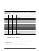
2.4 Physical organization Model Read/write heads Number of disks ST980817AM 2 1 ST980818AM 2 1 ST980817SM 2 1 ST980818SM 2 1 ST960817AM 2 1 ST960818AM 2 1 ST960817SM 2 1 ST960818SM 2 1 ST940817AM 1 1 ST940818AM 1 1 ST940817SM 1 1 ST940818SM 1 1 ST930817AM 1 1 ST930818AM 1 1 ST930817SM 1 1 ST930818SM 1 1 2.
2.6 Physical characteristics PATA SATA Height (mm) (inches) 9.5 +/–0.2 0.374 +/–0.008 9.5 +/–0.2 0.374 +/–0.008 Width (mm) (inches) 69.85 +/–0.25 2.750 +/–0.010 69.85 +/–0.25 2.750 +/–0.010 Length (mm) (inches) 100.2 +/–0.25 3.945 +/–0.010 100.5 +/- 1.58 3.957 +/- 0.062 Maximum weight (grams) (pounds) 102 0.22 102 0.22 2.7 Seek time Seek measurements are taken with nominal power. All times are measured using drive diagnostics.
2.8 Start/stop times Typical Max Power-on to ready -20 to 85°C for extreme models (75°C for rugged models) -30 to -20°C (extreme models only) 3 sigma maximum at extreme cold temperature 3.0 seconds 12 seconds - 5.0 seconds <30 seconds Standby to ready -20 to 85°C for extreme models (75°C for rugged models) -30 to -20°C (extreme models only) 3 sigma maximum at extreme cold temperature 3.0 seconds 12 seconds - 5.0 seconds <30 seconds Spin down (secs typical at 1 to 85°C) 5.0 8.
+5V Average Power dissipation 25C SATA Watts Amps Spinup, typical 5.0 1.0 Spinup, maximum 6.70 1.34 Idle, active* 2.35 0.47 Seeking 2.45 0.49 Read 3.00 0.60 Write 2.30 0.46 Standby 1.10 0.22 Sleep 1.10 0.22 Spinup, typical 5.0 1.0 Spinup, maximum 6.70 1.34 Idle, active* 1.65 0.33 Seeking 1.65 0.33 Read 1.40 0.28 Write 1.50 0.30 Standby 0.26 0.05 Sleep 0.26 0.05 PATA * 16 During periods of drive idle, some offline activity may occur according to the S.
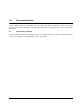
2.9.1.1 Typical current profile Figure 1. Typical 5V startup and operation current profile 2.9.2 Conducted noise Input noise ripple is measured at the host system power supply across an equivalent 15-ohm resistive load on the +5 volt line. Using 5-volt power, the drive is expected to operate with a maximum of 100 mV peak-to-peak square-wave injected noise at up to 10 MHz. Note. 2.9.3 Equivalent resistance is calculated by dividing the nominal voltage by the typical RMS read/write current.
2.9.4 Power-management modes The drive provides programmable power management to provide greater energy efficiency. In most systems, you can control power management through the system setup program. The drive features the following power-management modes: Power modes Heads Spindle Buffer Std timing Active (operating) Tracking Rotating Enabled Idle, performance Tracking Rotating Enabled Idle, active Floating Rotating Disabled 100ms Idle, low power Parked Rotating Disabled 5.
2.10 Environmental specifications 2.10.1 Ambient temperature Ambient temperature is defined as the temperature of the environment immediately surrounding the drive. Actual drive case temperature, measured on baseplate, should not exceed 90°C (194°F) within the operating ambient conditions. Operating Nonoperating 2.10.
2.11.1.2 Nonoperating shock The nonoperating shock level that the drive can experience without incurring physical damage or degradation in performance when subsequently put into operation is 800 Gs based on a nonrepetitive half-sine shock pulse of 2 msec duration. The nonoperating shock level that the drive can experience without incurring physical damage or degradation in performance when subsequently put into operation is 900 Gs based on a nonrepetitive half-sine shock pulse of 1 msec duration.
(Number of seeks per second = 0.4 / (average latency + average access time) Acoustic mode * Idle* Seeks 1.7 bels (typ) 1.9 bels (max) 1.9 bels (typ) 2.1 bels (max) During periods of drive idle, some offline activity may occur according to the S.M.A.R.T. specification, which may increase acoustic and power to operational levels. EE25.2 Series Product Manual, Rev.
2.
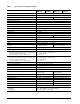
2.14 Reliability Measurement type Specification Nonrecoverable read errors 1 per 1014 bits read, max. Mean time between failures (MTBF) 1,000,000 power-on hours At 8,760 POH (Power On Hours) per year Max ambient air temperature: 25°C.
These drives have been tested and comply with the Electromagnetic Interference/Electromagnetic Susceptibility (EMI/EMS) for Class B products. Drives are tested in a representative, end-user system by a Korean-recognized lab.
2.16 Environmental protection Seagate designs its products to meet environmental protection requirements worldwide, including regulations restricting certain chemical substances. 2.16.1 European Union Restriction of Hazardous Substances (RoHS) The European Union Restriction of Hazardous Substances (RoHS) Directive restricts the presence of chemical substances, including Lead (Pb), in electronic products effective July 2006.
26 EE25.2 Series Product Manual, Rev.
3.0 Mounting and configuring the drive This section contains the specifications and instructions for mounting and configuring the drive. 3.1 Handling and static discharge precautions After unpacking, and before installation, the drive may be exposed to potential handling and electrostatic discharge (ESD) hazards.
1 DIMENSIONS PER EIA-720 OR SFF 8201 SPECIFICATION. 2 DIMENSIONS PER SFF 8212 OR SFF 8223. 3 DRIVE LENGTH W/ PATA IS 3.945±.057 (WORST CASE). DRIVE LENGTH W/ SATA IS 3.957±.062 (WORST CASE). 3.945 ± .010 (BASE) .157 ( .490 ) .217 ±.050 2 .217 ±.050 2 .399 C ( .673 ) OF CONN. DATUM B C OF DRIVE 1 2.750 ±.010 (BASE) ( .189 ) 2 SATA PATA 3 Recommended case temp. measurement location BASE 3.567 .551 1 1 2X M3 X 0.5-6H MOUNTING HOLES; BOTH SIDES .12 MIN FULL THREAD 0.148 ±.010 X 90 ( .
3.3 Breather filter hole precautions Observe the following breather filter hole precautions to ensure full functionality and prevent possible damage to the drive. Breather filter hole Do not cover, seal, or put any object in this hole. Figure 3 Breather filter hole location Caution: Do not cover, seal, or insert any object into this hole.
3.4 How to configure the drive See Section 3.4.1 beginning on page 30 for SATA drives. See Section 3.4.2 beginning on page 31 for PATA drives. 3.4.1 How to configure and connect Serial ATA (SATA) drives 3.4.1.1 How to configure the drive Each drive on the SATA interface connects in a point-to-point configuration with the SATA host adapter. There is no master/slave relationship because each drive is considered a master in a point-to-point relationships.
3.4.2 How to configure Parallel ATA (PATA) drives Use the options jumper block shown in Figure 6 to configure the drive for operation. This jumper block is the 4-pin header adjacent to pins 1 and 2 of the I/O signal pins. For additional information about using the Cable select option, see Section 3.4.2.1. Note. 3.4.2.1 Limit the number of PATA interface connector connects and disconnects to a maximum of 50 cycles.
32 EE25.2 Series Product Manual, Rev.
4.0 Interface Interface Refererence SATA See Section 4.1 beginning on page 34 PATA See Section 4.2 beginning on page 36 The following sections apply to both SATA and PATA drives: • Supported commands (See Section 4.3 beginning on page 37 ) • Identify Device command (See Section 4.4 beginning on page 39 ) • Set Features command (See Section 4.5 beginning on page 42 ) • S.M.A.R.T. commands (See Section 4.6 beginning on page 43 ) EE25.2 Series Product Manual, Rev.
4.1 Serial ATA (SATA) interface These drives use the industry-standard Serial ATA interface that supports FIS data transfers. It supports ATA programmed input/output (PIO) modes 0–4; multiword DMA modes 0–2, and Ultra DMA modes 0–6. The drive also supports the use of the IORDY signal to provide reliable high-speed data transfers. For detailed information about the Serial ATA interface, refer to the “Serial ATA: High Speed Serialized AT Attachment” specification. 4.1.1 Hot-Plug compatibility EE25.
Table 5: Segment Power Serial ATA connector pin definitions Pin Function Definition P1 V33 3.3V power P2 V33 3.3V power P3 V33 3.
4.2 Parallel ATA (ATA) interface These drives use the industry-standard ATA task file interface that supports 16-bit data transfers. It supports ATA programmed input/output (PIO) modes 0–4; multiword DMA modes 0–2, and Ultra DMA modes 0–5. The drive also supports the use of the IORDY signal to provide reliable high-speed data transfers.
4.3 Supported ATA commands The following table lists ATA-standard commands that the drive supports. For a detailed description of the ATA commands, refer to the ATA-6 Standard. EE25.2 Series drives support all standard 48-bit extended commands.
Command name Command code (in hex) Set Multiple Mode C6H Sleep 99H, E6H S.M.A.R.T.
4.4 Identify Device command The Identify Device command (command code ECH) transfers information about the drive to the host following power up. The data, shown below, is organized as a single 512-byte block of data. All reserved bits or words should be set to zero. Parameters listed with an “x” are drive-specific or vary with the state of the drive. See Section 2.0 on page 3 for default parameter settings.
Word Description Value 53 Words 54–58, 64–70 and 88 are valid 0007H 54 Number of current logical cylinders xxxxH 55 Number of current logical heads xxxxH 56 Number of current logical sectors per logical track xxxxH 57–58 Current capacity in sectors xxxxH 59 Number of sectors transferred during a Read Multiple or Write Multiple command xxxxH 60–61 Total number of user-addressable LBA sectors available (see Section 2.
Word Description Value 89 Security erase time 0000H 90 Enhanced security erase time 0000H 91 Advanced power management value 0040H 92 Master password revision code FFFEH 93 Hardware reset value (see description following this table) xxxxH 94 Auto acoustic management setting xxxxH 95–127 ATA-reserved 0000H 128 Security status 0001H 129–159 Seagate-reserved xxxxH 160–254 ATA-reserved 0000H 255 Integrity word xxA5H Note.
4.5 Set Features command This command controls the implementation of various features that the drive supports. When the drive receives this command, it sets BSY, checks the contents of the Features register, clears BSY and generates an interrupt. If the value in the register does not represent a feature that the drive supports, the command is aborted. Power-on default has the read look-ahead and write caching features enabled.
4.6 S.M.A.R.T. commands S.M.A.R.T. provides near-term failure prediction for disc drives. When S.M.A.R.T. is enabled, the drive monitors predetermined drive attributes that are susceptible to degradation over time. If self-monitoring determines that a failure is likely, S.M.A.R.T. makes a status report available to the host. Not all failures are predictable. S.M.A.R.T. predictability is limited to the attributes the drive can monitor. For more information on S.M.A.R.T.
44 EE25.2 Series Product Manual, Rev.
5.0 Seagate Technology support services Internet For information regarding Seagate products and services, visit www.seagate.com. Worldwide support is available 24 hours daily by email for your questions. Presales Support: Presales@Seagate.com Technical Support: DiscSupport@Seagate.com Warranty Support: http://www.seagate.com/support/service/index.html mySeagate my.seagate.com is the industry's first Web portal designed specifically for OEMs and distributors.
Customer Service Operations Warranty Service Seagate offers worldwide customer support for Seagate products. Seagate distributors, OEMs and other direct customers should contact their Seagate Customer Service Operations (CSO) representative for warrantyrelated issues. Resellers or end users of drive products should contact their place of purchase or Seagate warranty service for assistance. Have your serial number and model or part number available.
Index 3D Defense System 2 Download Microcode 35 Drive Defense 2 drive diagnostics 14 drive monitoring 2 drive self-test 2 A E acoustics 20 Active mode 18 agency certification (regulatory) 22 altitude 19 ambient conditions 3 ambient temperature 19 areal density 1, 13 ATA-standard commands 35 Australian C-Tick 23 autodetection 2 average seek time 14 electrical fast transient 21 electromagnetic compatibility 22 Electromagnetic Compatibility Directive 22 electromagnetic immunity 21 electrostatic discharge
interface signals 34 interference 23 interleave 13 internal data-transfer rate OD 13 ISO document 7779 20 K Korean RRL 22 L LBA mode 12 length 14 logical geometry 12 M master/slave 2 Master/slave configuration 29 Mean time between failures 22 modes 34 monitoring 2 mounting the drive 25 MTBF 22 N noise 17 nominal power 3 nonoperating shock 20 nonoperating vibration 20 nonrecoverable read errors 22 O operating shock 19 operating vibration 20 P physical characteristics 14 physical organization 13 pins 34
spinup power 15 Standby 16, 36 Standby Immediate 36 Standby mode 15, 18 static-discharge precautions 25 subassembly 23 support services 43 surge immunity 21 T technical support services 43 temperature 19 temperature gradient 19 time to ready 15 timers 18 track density 13 track-to-track seek time 14 TUV North America 22 U UL 1950 22 V vibration 20 voltage 17 voltage dips, interrupts 21 voltage tolerance 17 W Warranty 22 weight 14 wet bulb temperature 19 width 14 Write Buffer 36 Write DMA 36 Write Multipl
48 EE25.2 Series Product Manual, Rev.
Seagate Technology LLC 920 Disc Drive, Scotts Valley, California 95066-4544, USA Publication Number: 100448541, Rev. E, Printed in U.S.A.