Product Manual EE25 Series ST940813AM ST940814AM ST930813AM ST930814AM ST920813AM ST920814AM 100384290 Rev.
©2007, Seagate Technology LLC All rights reserved. Publication number: 100384290, Rev. E August 2007 Seagate, Seagate Technology and the Wave logo are registered trademarks of Seagate Technology LLC in the United States and/or other countries. EE25 Series, SeaTools and SeaTDD are either trademarks or registered trademarks of Seagate Technology LLC or one of its affiliated companies in the United States and/or other countries.
Contents 1.0 Introduction. . . . . . . . . . . . . . . . . . . . . . . . . . . . . . . . . . . . . . . . . . . . . . . . . . . . . . . . . . . . . . . . . . . 1 2.0 Drive specifications . . . . . . . . . . . . . . . . . . . . . . . . . . . . . . . . . . . . . . . . . . . . . . . . . . . . . . . . . . . . 3 2.1 Specification summary . . . . . . . . . . . . . . . . . . . . . . . . . . . . . . . . . . . . . . . . . . . . . . . . . . . . 3 2.2 Formatted capacity . . . . . . . . . . . . . . . . . . . . . . .
ii EE25 Series Product Manual, Rev.
List of Figures Figure 1. Figure 2. Figure 3. Figure 4. Typical 5V startup and operation current profile . . . . . . . . . . . . . . . . . . . . . . . . . . . . . . . . . . . Temperature vs. altitude capability . . . . . . . . . . . . . . . . . . . . . . . . . . . . . . . . . . . . . . . . . . . . . Jumper settings . . . . . . . . . . . . . . . . . . . . . . . . . . . . . . . . . . . . . . . . . . . . . . . . . . . . . . . . . . . Mounting dimensions—top, side and end view . . . . . . . . . . . . . . . . .
iv EE25 Series Product Manual, Rev.
1.
2 EE25 Series Product Manual, Rev.
2.0 Drive specifications Unless otherwise noted, all specifications are measured under ambient conditions, at 25°C, and nominal power. For convenience, the phrases the drive and this drive are used throughout this manual to indicate ST940813AM, ST940814AM, ST930813AM, ST930814AM, ST920813AM, and ST920814AM model drives. 2.1 Specification summary The specifications listed in the following two tables are for quick reference.
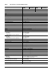
Table 1: Specifications for 40 and 30 Gbyte models Drive specification ST940813AM (OEM) Formatted (512 bytes/sector)* 40 Gbytes 30 Gbytes Guaranteed sectors 78,140,160 58,605,120 Bytes per sector 512 Physical read/write heads 2 Discs 1 Cache 8 Mbytes Recording density, BPI 540.1k bits/inch at ID Track density. TPI 119k tracks/inch at ID Areal density 64.3 Gbits/inch2 at ID Spindle speed 5,400 RPM Internal data transfer rate 321.
Drive specification ST940813AM (OEM) ST940814AM (Aftermarket) ST930813AM (OEM) ST930814AM (Aftermarket) Wet bulb temperature 40°C (operating, max) 40°C (nonoperating, max) Altitude, operating (at 25°C) –304.8 m to 4,419.6 m (–1000 ft to 14,500 ft) For higher temperature capabilities, See “Temperature vs. altitude capability” on page 15. Altitude, nonoperating (below mean sea level, max) –304.
Table 2: Specifications for 20 Gbyte models Drive specification ST920813AM (OEM) ST920814AM (Aftermarket) Formatted (512 bytes/sector)* 20 Gbytes Guaranteed sectors 39,070,080 Bytes per sector 512 Physical read/write heads 1 Discs 1 Cache 8 Mbytes Recording density, BPI 540.1k bits/inch at ID Track density. TPI 119k tracks/inch at ID Areal density 64.3 Gbits/inch2 at ID Spindle speed 5,400 RPM Internal data transfer rate 321.
Drive specification ST920813AM (OEM) ST920814AM (Aftermarket) Wet bulb temperature 40°C (operating, max) 40°C (nonoperating, max) Altitude, operating (at 25°C) –304.8 m to 4,419.6 m (–1000 ft to 14,500 ft) For higher temperature capabilities, See “Temperature vs. altitude capability” on page 15. Altitude, nonoperating (below mean sea level, max) –304.8 m to 12,192 m (–1,000 ft to 40,000 ft) Shock, operating at 2 msec at 11 msec 200 Gs max 110 Gs max Shock, nonoperating at 2 msec at 1 msec at 0.
2.2 Formatted capacity Model Formatted capacity* Guaranteed sectors Bytes per sector ST940813AM 40 Gbytes 78,140,160 512 ST940814AM 40 Gbytes 78,140,160 512 ST930813AM 30 Gbytes 58,605,120 512 ST930814AM 30 Gbytes 58,605,120 512 ST920813AM 20 Gbytes 39,070,080 512 ST920814AM 20 Gbytes 39,070,080 512 *One Gbyte equals one billion bytes when referring to hard drive capacity. Accessible capacity may vary depending on operating environment and formatting. 2.
2.5 Recording and interface technology Technology Specification Interface Parallel ATA Recording density BPI 540.1k bits/inch typical Track density TPI 119k tracks/inch typical Areal density 64.3 Gbits/inch2 max Spindle speed 5,400 RPM (± 0.2%) Internal data-transfer rate 321.1 Mbits/sec max I/O data transfer rate 100 Mbytes/sec max Interleave 1:1 Cache buffer 8 Mbytes (8,192 kbytes) 2.6 Physical characteristics Height (mm) (inches) 9.5 +/–0.2 0.374 +/–0.
Read seek times vs temperature 85°C 25°C -20°C -30°C msec msec msec msec Typical Max Typical Max Typical Max Typical Max Track-to-track 1 1 0.5 1 0.5 6 1 6 Average 11 15 11 13 11 14 11 17 Full-stroke 22 28 22 24 22 28 23 29 Average latency 5.6 5.6 5.6 5.
2.9 Power specifications The drive receives DC power (+5V) through the interface connector. 2.9.1 Power consumption Power requirements for the drives are listed in the table on page 11. Typical power measurements are based on an average of drives tested, under nominal conditions, using 5.0V input voltage at 25°C ambient temperature. • Spinup power Spinup power is measured from the time of power-on to the time that the drive spindle reaches operating speed.
2.9.1.1 Typical current profile Figure 1. Typical 5V startup and operation current profile 2.9.2 Conducted noise Input noise ripple is measured at the host system power supply across an equivalent 15-ohm resistive load on the +5 volt line. Using 5-volt power, the drive is expected to operate with a maximum of 100 mV peak-to-peak square-wave injected noise at up to 10 MHz. Note. 2.9.3 Equivalent resistance is calculated by dividing the nominal voltage by the typical RMS read/write current.
2.9.4 Power-management modes The drive provides programmable power management to provide greater energy efficiency. In most systems, you can control power management through the system setup program.
2.10 Environmental specifications 2.10.1 Ambient temperature Ambient temperature is defined as the temperature of the environment immediately surrounding the drive. Actual drive case temperature, measured on baseplate, should not exceed 90°C (194°F) within the operating ambient conditions. Operating Nonoperating 2.10.
5500 75C 5000 Altitude (m) 4500 4000 85C 3500 3000 2500 -30 -10 10 30 50 70 90 Temperature (degrees C) Altitude (m) Figure 2. Temperature vs. altitude capability 2.11.1 Shock All shock specifications assume that the drive is mounted securely with the input shock applied at the drive mounting screws. Shock may be applied in the X, Y or Z axis. 2.11.1.
2.11.2 Vibration All vibration specifications assume that the drive is mounted securely with the input vibration applied at the drive mounting screws. Vibration may be applied in the X, Y or Z axis. 2.11.2.1 Operating vibration The following table lists the maximum vibration levels that the drive may experience while meeting the performance standards specified in this document. 10–200 Hz 2.0 G (0 to peak) 200–500 Hz 1.0 G (0 to peak) 2.11.2.
2.
2.15 Agency certification 2.15.1 Safety certification The drives are recognized in accordance with UL 1950 and CSA C22.2 (950) and meet all applicable sections of IEC950 and EN 60950 as tested by TUV North America. 2.15.2 Electromagnetic compatibility Hard drives that display the CE mark comply with the European Union (EU) requirements specified in the Electromagnetic Compatibility Directive (89/336/EEC).
Radio and television interference. This equipment generates and uses radio frequency energy and if not installed and used in strict accordance with the manufacturer’s instructions, may cause interference to radio and television reception. This equipment is designed to provide reasonable protection against such interference in a residential installation. However, there is no guarantee that interference will not occur in a particular installation.
exposed to an ambient relative humidity greater than 95%. Materials used in cabinet fabrication, such as vulcanized rubber, that can outgas corrosive compounds should be minimized or eliminated. The useful life of any electronic equipment may be extended by replacing materials near circuitry with sulfide-free alternatives. 20 EE25 Series Product Manual, Rev.
3.0 Configuring and mounting the drive This section contains the specifications and instructions for configuring and mounting the drive. 3.1 Handling and static discharge precautions After unpacking, and before installation, the drive may be exposed to potential handling and electrostatic discharge (ESD) hazards.
3.2.2 Cable-select option Computers that use cable select determine the master and slave drives by selecting or deselecting pin 28, CSEL, on the interface bus. Master and slave drives are determined by their physical position on the cable. To enable cable select, set a jumper as shown in Figure 3. Refer to your computer manual to determine whether your computer supports this option. 3.
4.0 ATA interface These drives use the industry-standard ATA task file interface that supports 16-bit data transfers. It supports ATA programmed input/output (PIO) modes 0–4; multiword DMA modes 0–2, and Ultra DMA modes 0–5. The drive also supports the use of the IORDY signal to provide reliable high-speed data transfers. For detailed information about the ATA interface, refer to the AT Attachment - 6 with Packet Interface (ATA/ ATAPI-6), ANSI NCITS 361-200, subsequently referred to as the ATA-6 Standard.
4.1.1 Supported ATA commands The following table lists ATA-standard commands that the drive supports. For a detailed description of the ATA commands, refer to the ATA-6 Standard.
Command name Note: Individual Set Max commands are identified by the value placed in the Set Max Features register as defined to the right. Command code (in hex) Address Password Lock Unlock Freeze Lock Set Multiple Mode C6H Sleep 99H, E6H S.M.A.R.T.
4.1.2 Identify Device command The Identify Device command (command code ECH) transfers information about the drive to the host following power up. The data, shown below, is organized as a single 512-byte block of data. All reserved bits or words should be set to zero. Parameters listed with an “x” are drive-specific or vary with the state of the drive. See Section 2.0 on page 3 for default parameter settings.
Word Description Value 57–58 Current capacity in sectors xxxxH 59 Number of sectors transferred during a Read Multiple or Write Multiple command xxxxH 60–61 Total number of user-addressable LBA sectors available (see Section 2.
Word Description Value 129–159 Seagate-reserved xxxxH 160–254 ATA-reserved 0000H 255 Integrity word xxA5H Note. See the bit descriptions below for words 63, 88, 93 and 94 of the Identify Drive data. Description (if bit is set to 1) 28 Bit Word 63 0 Multiword DMA mode 0 is supported. 1 Multiword DMA mode 1 is supported. 2 Multiword DMA mode 2 is supported. 8 Multiword DMA mode 0 is currently active. 9 Multiword DMA mode 1 is currently active.
4.1.3 Set Features command This command controls the implementation of various features that the drive supports. When the drive receives this command, it sets BSY, checks the contents of the Features register, clears BSY and generates an interrupt. If the value in the register does not represent a feature that the drive supports, the command is aborted. Power-on default has the read look-ahead and write caching features enabled.
30 EE25 Series Product Manual, Rev.
5.0 Seagate Technology support services Internet For information regarding Seagate products and services, visit www.seagate.com. Worldwide support is available 24 hours daily by email for your questions. Presales Support: Presales@Seagate.com Technical Support: DiscSupport@Seagate.com Warranty Support: http://www.seagate.com/support/service/index.html mySeagate my.seagate.com is the industry's first Web portal designed specifically for OEMs and distributors.
Customer Service Operations Warranty Service Seagate offers worldwide customer support for Seagate products. Seagate distributors, OEMs and other direct customers should contact their Seagate Customer Service Operations (CSO) representative for warrantyrelated issues. Resellers or end users of drive products should contact their place of purchase or Seagate warranty service for assistance. Have your serial number and model or part number available.
Index Numerics 3D Defense System 1 A acoustics 16 Active mode 13 agency certification (regulatory) 18 altitude 14 ambient conditions 3 ambient temperature 14 areal density 9 ATA interface 23 ATA-standard commands 24 Australian C-Tick 18 autodetection 1 average seek time 9 B BPI 9 buffer 1, 9 burst 1 C cable select 1 cable-select option 22 cache 1, 9 case temperature 14 CE mark 18 certification 18 Check Power Mode 25 commands 24 compliance 18 conducted noise 12 conducted RF immunity 17 configuring the dri
interface signals 23 interference 18 interleave 9 internal data-transfer rate OD 9 ISO document 7779 16 J jumper settings 21 K Korean RRL 18 L LBA mode 8 length 9 Load/Unload 17 logical geometry 8 M master/slave 1 Master/slave configuration 21 Mean time between failures 17 modes 23 monitoring 1 mounting the drive 21, 22 MTBF 17 N noise 12 nominal power 3 nonoperating shock 15 nonoperating vibration 16 nonrecoverable read errors 17 O operating shock 15 operating vibration 16 P physical characteristics
Sleep 11, 25 Sleep mode 13 sound 16 specifications 3 Spin down 10 spindle speed 9 Spinup 11 spinup power 11 Standby 11, 25 Standby Immediate 25 Standby mode 11, 13 static-discharge precautions 21 subassembly 18 support services 31 surge immunity 17 T technical support services 31 temperature 14 temperature gradient 14 time to ready 10 timers 13 TMR 1 track density 9 track-to-track seek time 9 TUV North America 18 U UL 1950 18 V vibration 16 voltage 12 voltage dips, interrupts 17 voltage tolerance 12 W W
36 EE25 Series Product Manual, Rev.
Seagate Technology LLC 920 Disc Drive, Scotts Valley, California 95066-4544, USA Publication Number: 100384290, Rev. E, Printed in U.S.A.