
Installation guide


Hawk 2LP (Wide) Installation Guide, Rev. A 35
A
F
D
E
[1]
[3]
B
G
Inches
A
B
C
D
E
F
G
H
J
K
L
145.80
101.60
25.40
60.00
15.75
101.60
6.35
44.45
95.25
60.20
4.597
J
H
K
[2]
5.74
4.00
1.00
2.362
.620
4.000
.250
1.750
3.750
2.370
0.181
± .010
± .010
+ .026
– .010
± .010
± .010
± .010
+ .010
– .005
± .010
± .010
± .010
+ .018
– .013
± .25
± .25
+ .66
– .25
± .25
± .25
± .25
+ .25
– .12
± .25
± .25
± .25
+ .45
– .33
Millimeters
C
L
Connector Centerline
[4]
Pin 1
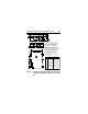
Notes:
[1]
[2]
[3]
[4]
Mounting holes three on each side, 6-32
UNC. Max screw length into side of drive
0.15 in. (3.81 mm). Screw tightening
torque 6.0 in-lb (.675 NM) max with
minimum thread engagement of 0.12 in.
(3.05 mm).
Mounting holes four on bottom, 6-32 UNC.
Max screw length into bottom of drive
0.20 in. (5.08 mm). Screw tightening torque
6.0 in-lb (.675 NM) max with minimum
thread engagement of 0.12 in. (3.05 mm).
Power and interface connections can
extend past the "A" dimension by
0.040 in. (1.02 mm).
Connector is centered on drive within
±0.020 in. (.508 mm).
Figure 5. Hawk 2LP family WC and DC model mounting
configuration dimension (80 pin I/O connec-
tor)