
Specifications


38 Hawk 2XL Product Manual, Rev. B
8.2 Drive orientation
The balanced rotary arm actuator design of the drive allows it to be mounted in any orientation. All drive perfor-
mance characterization, however, has been done with the drive in horizontal (discs level) and vertical (drive on
its side) orientations, and these are the two preferred mounting orientations.
8.3 Cooling
Cabinet cooling must be designed by the customer so that the ambient temperature immediately surrounding
the drive will not exceed temperature conditions specified in Section 6.4.1, “Temperature.” Specific consider-
ation should be given to make sure adequate air circulation is present around the printed circuit board (PCB) to
meet the requirements of Section 6.4.1, “Temperature.”
8.3.1 Air flow
The rack, cabinet, or drawer environment for the Hawk 2XL drive must provide cooling of the electronics and
head and disc assembly (HDA). You should confirm that adequate cooling is provided using the temperature
measurement guidelines described below.
The drive should be oriented, or air flow directed, so that the least amount of air flow resistance is created
while providing air flow to the electronics and HDA. Also, the shortest possible path between the air inlet and
exit should be chosen to minimize the travel length of air heated by the drive and other heat sources within the
rack, cabinet, or drawer environment.
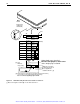
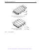
Possible air-flow patterns are shown in Figure 8. The air-flow patterns are created by one or more fans, either
forcing or drawing air as shown in the illustrations. Other air-flow patterns are acceptable as long as the tem-
perature measurement guidelines of Section 6.4.1 are met.
8.4 Drive mounting
When mounting the drive using the bottom holes (x-y plane in Figure 5) care must be taken to ensure that the
drive is not physically distorted due to a stiff non-flat mounting surface. The allowable mounting surface
stiffness is 80 lb/in (14.0 N/mm). The following equation and paragraph define the allowable mounting surface
stiffness:
k * x = 80 lb (14.0 N)
where ‘k’ represents the mounting surface stiffness (units of lb/in or N/mm), and, ‘x’ represents the out-of-plane
mounting surface distortion (units of inches or millimeters). The out-of-plane distortion (‘x’) is determined by
defining a plane with three of the for mounting points fixed and evaluating the out-of-plane deflection of the
fourth mounting point when a known force is applied to the fourth point.
8.5 Grounding
Signal ground (PCB) and HDA ground are connected together in the drive and cannot be separated by the
user. The equipment in which the drive is mounted is connected directly to the HDA and PCB with no electri-
cally isolating shock mounts. If it is desired for the system chassis to not be connected to the HDA/PCB
ground, the systems integrator or user must provide a nonconductive (electrically isolating) method of mount-
ing the drive in the host equipment.
Artisan Scientific - Quality Instrumentation ... Guaranteed | (888) 88-SOURCE | www.artisan-scientific.com