
Specifications
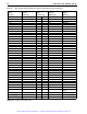


62 Hawk 2XL Product Manual, Rev. B
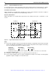
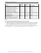
9.6.4.4 Single-ended drivers/receivers
For “N” models which use single-ended drivers and receivers, typical circuits are shown in Figure 12. Termina-
tor circuits (Note [1]) are to be enabled (model N) only when the disc drive is first or last in the daisy-chain.
Transmitter characteristics
Single-ended drives use an ANSI SCSI compatible open collector single-ended driver. This driver is capable of
sinking a current of 48 mA with a low level output voltage of 0.4 volt.
Receiver characteristics
Single-ended drives use an ANSI SCSI single-ended receiver with hysteresis gate or equivalent as a line
receiver.
Figure 12. Single-ended transmitters and receivers
Notes.
[1] Part of active terminator circuits. Non-removable LSI terminators, enabled in the drive (model “N” and “W”
models only) with jumper plug TE when it is first of last in the daisy-chain. Interface signals levels and log-
ical sense at the drive I/O connector are defined as follows:
The difference in the voltages between input and output signals is due to the losses in the cable.
[2] ANSI SCSI compatible circuits
[3] Total interface cable length should not exceed that specified in Section 9.6.3.1.
[4] Source of drive terminator power is an active circuit which has an input source voltage selected by jumper
plug TP. See Figure 7d. Applies to “N” and “W” models.
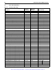
Logic Level Driver Output Receiver Input
NEGATED (0) >2.5 V: <5.25 V >2.0 V: <5.25 V
ASSERTED (1) <
0.4 V: >0.0 V <0.8 V: >0. 0 V
Transmitter
(or transceiver)
Line Driver
Flat
Cable
Pair
[3]
[2]
[4]
[1]
110
Ohm
[4]
[1]
110
Ohm
Receiver
Line Receiver
[2]
TP TP
Artisan Scientific - Quality Instrumentation ... Guaranteed | (888) 88-SOURCE | www.artisan-scientific.com