
Installation guide

DC Power
Connector
Pin
1P
2P
3P
4P
Power
+12V
+12V ret
+ 5V ret
+ 5V
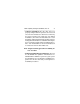
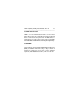
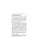
J1
1P2P3P4P
68 Pin SCSI I/O
Connector
J1-Auxiliary
18 Hawk 4 (Wide) Family Install Guide, Rev. A
___________________________________________
Figure 1. DC power connection, 68 pin SCSI I/O
connector
ST15230WC and ST15230DC model drives receive
power from the host computer through the 80 pin
combined SCSI I/O and power connector (not shown,
since a separate DC power cable not required). No
separate DC power connector is provided on the drive.
SCSI address selection
On "W" and "WD" model drives, make sure that the
SCSI bus address jumper plugs are properly set for the
bus address assigned to the drive. In some systems, a
cable plugs into either J6 or J1auxiliary, so drive ID can
be set at some remote location. See Figures 3a and 3b
showing the bus address select header and the jumper
configurations that select addresses 0 through 15. ID 7
has the highest priority during bus arbitration on (both
8 and 16 device systems). Bus arbitration priority
decreases to ID 0, then ID 15 down to ID 8. ID 8 is the
very lowest priority. Typically the primary boot device is
set to ID 0 the host is ID 7, and the subsequent SCSI
drives are jumpered as appropriate for the particular
system involved.