..................................... Medalist 3240 ..................................... Medalist 2531 ..................................... ATA Interface Drives ..................................... ..................................... Product Manual .....................................
..................................... Medalist 3240 (ST33240A) ..................................... Medalist 2531 (ST32531A) ..................................... ATA Interface Drives ..................................... ..................................... Product Manual .....................................
1997 Seagate Technology, Inc. All rights reserved Publication Number: 20401033-001, Rev. A, March 1997 Seagate, Seagate Technology, the Seagate logo, Medalist and the Medalist logo are either trademarks or registered trademarks of Seagate Technology, Inc. Other product names are registered trademarks or trademarks of their owners. Seagate reserves the right to change, without notice, product offerings or specifications.
Medalist 3240 and Medalist 2531 Product Manual, Rev. A iii Contents Introduction . . . . . . . . . . . . . . . . . . . . . . . . . . . . 1 Specification summary table . . . . . . . . . . . . . . . . . . . 2 1.0 Drive specifications . . . . . . . . . . . . . . . . . . . . . . 5 1.1 Formatted capacity . . . . . . . . . . . . . . . . . . . . . 5 1.1.1 Default logical geometry . . . . . . . . . . . . . . . . 5 1.1.2 Supported CHS translation geometries . . . . . . . . 5 1.2 Physical organization . . . . .
iv Medalist 3240 and Medalist 2531 Product Manual, Rev. A 1.12.2 Electromagnetic Compatibility . . . . . . . . . . . . 14 1.12.3 FCC verification . . . . . . . . . . . . . . . . . . . . 14 2.0 Drive mounting and configuration . . . . . . . . . . . . . . 17 2.1 Handling and static-discharge precautions . . . . . . . . . 17 2.2 Jumper settings . . . . . . . . . . . . . . . . . . . . . . . 17 2.2.1 Master/slave configuration . . . . . . . . . . . . . . . 17 2.2.2 Alternate capacity jumper 2.
Medalist 3240 and Medalist 2531 Product Manual, Rev. A v Figures Figure 1. Typical startup and operation current profile . . . . . . . 9 Figure 2. Master/slave jumpers and alternate capacity jumper . . 18 Figure 3. Drive mounting dimensions—top, end and side view . . . 19 Figure 4. I/O pins and supported ATA signals . . . . . . . . . . .
vi Medalist 3240 and Medalist 2531 Product Manual, Rev.
Medalist 3240 and Medalist 2531 Product Manual, Rev. A 1 Introduction The Medalist® 3240 (ST33240A) and Medalist 2531 (ST32531A) provide the following key features: • Low power consumption • Quiet operation • Support for S.M.A.R.T drive monitoring and reporting • High instantaneous (burst) data-transfer rates (up to 16.
2 Medalist 3240 and Medalist 2531 Product Manual, Rev. A Specification summary table The specifications listed in this table are for quick reference. For details on specification measurement or definition, see the appropriate section of this manual.
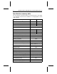
Medalist 3240 and Medalist 2531 Product Manual, Rev. A Drive Specification Startup current: 12V (peak) 5V (RMS) ST33240A 3 ST32531A 1.6 amps 0.5 amps Seek power (mean) 4.3 watts Operating power (typical) 4.6 watts Idle mode power (typical) 4.5 watts Standby mode power (typical) 1.0 watts Sleep mode power (typical) 0.7 watts Voltage tolerance (including noise) Ambient temperature (°C) Temperature gradient (°C per hour max) Relative humidity (op. and nonop.) ± 5% 5 to 55 (op.
4 Medalist 3240 and Medalist 2531 Product Manual, Rev.
Medalist 3240 and Medalist 2531 Product Manual, Rev. A 5 1.0 Drive specifications Unless otherwise noted, all specifications are measured under ambient conditions, at 25°C, and nominal power. For convenience the phrases the drive and this drive are used throughout this manual to indicate both the ST33240A and the ST32531A. 1.1 Formatted capacity ST33240A ST32531A Guaranteed Mbytes (1 Mbyte = 106 bytes) 3,227 2,557 Guaranteed sectors 6,303,024 4,995,648 Bytes per sector 512 512 Note.
6 Medalist 3240 and Medalist 2531 Product Manual, Rev. A The ST32531A supports any translation geometry that satisfies the sectors and head limitations above, and • (Sectors per track) × (Read/Write heads) × (cylinders) ≤4,995,648 1.2 Physical organization ST33240A ST32531A Read/Write heads 8 6 Discs 4 3 1.
Medalist 3240 and Medalist 2531 Product Manual, Rev. A 7 1.5 Seek time All seek times are measured using a 486 AT computer (or faster) with an 8.3 MHz I/O bus. The measurements are taken with nominal power at sea level and 25°C ambient temperature. All times are measured using drive diagnostics. The specifications in the table below are defined as follows: • Track-to-track seek time is an average of all possible single-track seeks in both directions.
8 Medalist 3240 and Medalist 2531 Product Manual, Rev. A 1.7 Power specifications The drive receives DC power (+5V or +12V) through a four-pin standard drive power connector. 1.7.1 Power consumption Power requirements for the drive are listed in the table below. Typical power measurements are based on an average of drives tested under nominal conditions, using 5.0V and 12.0V input voltages at room temperature.
Medalist 3240 and Medalist 2531 Product Manual, Rev. A 1.7.1.1 9 Typical current profile Current (mA) 1,400 1,200 1,000 800 600 400 200 0 2 4 6 8 10 12 14 Time (seconds) 16 18 Figure 1. Typical startup and operation current profile Figure 1 shows a typical current profile for the Medalist 3240 and the Medalist 2531. 1.7.
10 1.7.4 Medalist 3240 and Medalist 2531 Product Manual, Rev. A Power-management modes This drive provides programmable power management to provide greater energy efficiency. In most systems, you can control power management through the system setup program.
Medalist 3240 and Medalist 2531 Product Manual, Rev. A 11 any drive activity is required, the drive makes a transition to Idle mode. If the host has set the standby timer, the standby countdown continues. If the host has not set the standby timer, the drive remains in Idle mode. If the standby timer reaches zero before any drive activity is required, the drive makes a transition to Standby mode.
12 Medalist 3240 and Medalist 2531 Product Manual, Rev. A 1.8.5 Shock For all shock specifications, it is assumed that the drive is mounted securely with the input shock applied at the drive mounting screws. Shock may be applied in the X, Y or Z axis. For the nonoperating specifications, it is assumed that the read/write heads are positioned in the shipping zone. Note. At power-down, the read/write heads automatically move to the shipping zone.
Medalist 3240 and Medalist 2531 Product Manual, Rev. A 1.8.6.2 13 Nonoperating vibration The following table lists the maximum nonoperating vibration that the drive may experience without incurring physical damage or degradation in performance when subsequently put into operation. 5–22 Hz 0.081-inch displacement (peak to peak) 22–350 Hz 5 Gs acceleration (zero to peak) 1.9 Drive acoustics Drive acoustics are measured as overall A-weighted acoustic sound power levels (no pure tones).
14 Medalist 3240 and Medalist 2531 Product Manual, Rev. A Contact start-stop cycles 40,000 cycles (at nominal voltage and temperature, with 60 cycles per hour and a 50% duty cycle) Preventive maintenance None required 1.12 Agency certification 1.12.1 Safety certification The drive is recognized in accordance with UL 1950 and CSA C22.2 (950) and meets all applicable sections of IEC 950 and EN 60950 as tested by TUV North America. 1.12.
Medalist 3240 and Medalist 2531 Product Manual, Rev. A 15 Radio and Television Interference. This equipment generates and uses radio frequency energy and if not installed and used in strict accordance with the manufacturer’s instructions, may cause interference to radio and television reception. This equipment is designed to provide reasonable protection against such interference in a residential installation. However, there is no guarantee that interference will not occur in a particular installation.
16 Medalist 3240 and Medalist 2531 Product Manual, Rev.
Medalist 3240 and Medalist 2531 Product Manual, Rev. A 17 2.0 Drive mounting and configuration 2.1 Handling and static-discharge precautions After unpacking, and before installation, the drive may be exposed to potential handling and electrostatic discharge (ESD) hazards. You must observe standard static-discharge precautions. A grounded wrist-strap is preferred. Handle the drive only by the sides of the head/disc assembly.
Medalist 3240 and Medalist 2531 Product Manual, Rev. A 4 3 2 1 18 3 1 4 2 pin 1 Alternative capacity jumper 4-pin power connector Master/slave jumper settings Full capacity (as shipped) Limit capacity to 2.1 Gbytes (4,092 cylinders)1 1. Use this jumper setting if your computer fails to boot because it cannot address drives with more than 4,096 cylinders.
Medalist 3240 and Medalist 2531 Product Manual, Rev. A Note: Units are in inches (mm) Tolerances: 0.xx ± 0.01 0.xxx ± 0.005 0.230 ± 0.015 (5.84 ± 0.38) 1.00 ± 0.03 (25.4 ± 0.8) 19 0.180 ± 0.015 (4.57 ± 0.38) 2.23 ± 0.03 (56.6 ± 0.8) 3x 6-32 UNC-2B max. insertion depth 0.14 (3.6) both sides 3.72 ± 0.03 (94.5 ± 0.8) 4X 6-32 UNC-2B max. insertion depth 0.22 (5.6) 4.000 ± 0.010 (101.60 ± 0.25) 1.750 ± 0.010 (44.45 ± 0.25) 5.75 ± 0.03 (146.1 ± 0.8) 2.362 ± 0.010 (59.99 ± 0.25) 2.375 +0.030, –0.005 (60.
20 Medalist 3240 and Medalist 2531 Product Manual, Rev.
Medalist 3240 and Medalist 2531 Product Manual, Rev. A 21 3.0 ATA interface This drive uses the industry-standard ATA task file interface. It supports both 8-bit and 16-bit data transfers. It supports ATA programmed input/output (PIO) modes 0, 1, 2, 3 and 4; ATA single-word DMA modes 0, 1 and 2; and ATA multiword DMA modes 0, 1 and 2. The drive also supports the use of the IORDY signal to provide reliable high-speed data transfers.
22 Medalist 3240 and Medalist 2531 Product Manual, Rev.
Medalist 3240 and Medalist 2531 Product Manual, Rev. A 23 3.2 ATA Interface commands 3.2.1 Supported ATA commands The following table lists ATA-standard commands that the drive supports. For a detailed description of the ATA commands, refer to the Draft Proposed ATA-3 Standard. See section 3.2.4 on page 29 for details and subcommands used in the S.M.A.R.T. implementation. Command name Command code Supported by this drive ATA-standard commands Execute Drive Diagnostics 90H Yes Execute S.M.A.R.T.
24 Medalist 3240 and Medalist 2531 Product Manual, Rev.
Medalist 3240 and Medalist 2531 Product Manual, Rev. A 25 The following commands contain drive-specific features that may not be described in the Draft Proposed ATA-3 Standard. 3.2.2 Identify Drive command The Identify Drive command (command code ECH) transfers information about the drive to the host following power up. The data is organized as a single 512-byte block of data, whose contents are shown in the table below. All reserved bits or words should be set to zero.
26 Medalist 3240 and Medalist 2531 Product Manual, Rev. A continued from previous page Word Description Contents 20 Controller type = dual-port multisector buffer with caching (not used) 0000H 21 Buffer size (not used) 0000H 22 Number of ECC bytes available (4) 0004H 23–26 Firmware revision (8 ASCII character string): x.
Medalist 3240 and Medalist 2531 Product Manual, Rev.
28 3.2.3 Medalist 3240 and Medalist 2531 Product Manual, Rev. A Set Features command This command controls the implementation of various features that the drive supports. When the drive receives this command, it sets BSY, checks the contents of the Features register, clears BSY and generates an interrupt. If the value in the register does not represent a feature that the drive supports, the command is aborted.
Medalist 3240 and Medalist 2531 Product Manual, Rev. A 3.2.4 29 S.M.A.R.T. commands Self-Monitoring, Analysis and Reporting Technology (S.M.A.R.T.) is an emerging technology that provides near-term failure prediction for disc drives. When S.M.A.R.T. is enabled, the Seagate drive monitors predetermined drive attributes that are susceptible to degradation over time. If a failure is likely to occur, S.M.A.R.T.
30 Medalist 3240 and Medalist 2531 Product Manual, Rev. A Code in Features Register S.M.A.R.T. Command Supported by Medalist 3240 and Medalist 2531 DBH Enable/disable Automatic Off-line Yes Note. If an appropriate code is not written to the Features Register, the command will be aborted and 0x04 (abort) will be written to the Error register.
Seagate Technology, Inc. 920 Disc Drive, Scotts Valley, California 95066, USA Publication Number: 20401033-001, Rev.