Product Manual Momentus 5400.3 SATA Blade Server ® ST9160821SB ST9120822SB ST9100828SB ST980815SB ST960815SB ST9402116SB 100418128 Rev.
©2004-2007, Seagate Technology LLC All rights reserved. Publication number: 100418128, Rev. E August 2007 Seagate, Seagate Technology and the Wave logo are registered trademarks of Seagate Technology LLC in the United States and/or other countries. Momentus, SeagateSeaBOARD, SeaFONE, SeaTDD, and SeaTools are either trademarks or registered trademarks of Seagate Technology LLC or one of its affiliated companies in the United States and/ or other countries.
Contents 1.0 Introduction. . . . . . . . . . . . . . . . . . . . . . . . . . . . . . . . . . . . . . . . . . . . . . . . . . . . . . . . . . . . . . . . . . . 1 1.1 About the Serial ATA interface . . . . . . . . . . . . . . . . . . . . . . . . . . . . . . . . . . . . . . . . . . . . . . 2 2.0 Drive specifications . . . . . . . . . . . . . . . . . . . . . . . . . . . . . . . . . . . . . . . . . . . . . . . . . . . . . . . . . . . . 3 2.1 Specification summary table . . . . . . . . . . . . . . . . . . . .
ii Momentus 5400.3 SATA Blade Server Product Manual, Rev.
List of Figures Figure 1. Figure 2. Figure 3. Figure 4. Typical +5V startup and operation current profile . . . . . . . . . . . . . . . . . . . . . . . . . . . . . . . . . . . 8 Serial ATA connectors . . . . . . . . . . . . . . . . . . . . . . . . . . . . . . . . . . . . . . . . . . . . . . . . . . . . . . 18 Attaching SATA cabling . . . . . . . . . . . . . . . . . . . . . . . . . . . . . . . . . . . . . . . . . . . . . . . . . . . . . 18 Mounting dimensions—top, side and end view . . . . . . . . . . . . .
1.0 Introduction This manual describes the functional, mechanical and interface specifications for the following Seagate Momentus® 5400.3 SATA Blade Server model drives: • ST9160821SB • ST9120822SB • ST9100828SB • ST980815SB • ST960815SB • ST9402116SB These drives provide the following key features: • 5,400 RPM spindle speed. • 8-Mbyte buffer. • Quiet operation. Fluid Dynamic Bearing (FDB) motor. • High instantaneous (burst) data-transfer rates (up to 150 Mbytes per second).
1.1 About the Serial ATA interface The Serial ATA interface provides several advantages over the traditional (parallel) ATA interface. The primary advantages include: • Easy installation and configuration with true plug-and-play connectivity. It is not necessary to set any jumpers or other configuration options. • Thinner and more flexible cabling for improved enclosure airflow and ease of installation. • Scalability to higher performance levels.
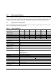
2.0 Drive specifications Unless otherwise noted, all specifications are measured under ambient conditions, at 25°C, and nominal power. For convenience, the phrases the drive and this drive are used throughout this manual to indicate the ST9160821SB, ST9120822SB, ST9100828SB, ST980815SB, ST960815SB, and ST9402116SB models. 2.1 Specification summary table The specifications listed in this table are for quick reference.
Table 1: Drive specifications Drive specification ST9160821SB ST9120822SB ST9100828SB ST980815SB Average seek, read (msec typical) 11.0 Average seek, write (msec typical) 13.0 Average random seek (msec) 12.5 Full-stroke seek (msec) 22 (typical); 24 (max) Startup current, +5V (typical) 1.0 amps Seek power (typical) 2.0 watts Read/write power (typical) Read: 1.9 watts; Write: 1.8 watts Idle mode, low power (typical) 0.6 watts Standby mode 0.2 watts (typical)** Sleep mode 0.
Table 1: Drive specifications Drive specification ST9160821SB ST9120822SB ST9100828SB ST980815SB ST960815SB ST9402116SB Warranty 5 years on distribution units. To determine the warranty for a specific drive, use a web browser to access the following web page: www.seagate.com/support/service/ From this page, click on the “Verify Your Warranty” link. You will be asked to provide the drive serial number, model number (or part number) and country of purchase.
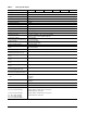
2.4 Physical organization Drive model Read/write heads Number of discs ST9160821SB 4 2 ST9120822SB 3 2 ST9100828SB 3 2 ST980815SB 2 1 ST960815SB 2 1 ST9402116SB 1 1 2.5 Recording and interface technology Interface Serial ATA (SATA) Recording method Perpendicular Recording density BPI (bits/inch max) 870k Track density TPI (tracks/inch max) 150k Areal density (Gbits/inch2 max) 132 Spindle speed (RPM) (± 0.
2.7 Seek time Seek measurements are taken with nominal power at 25°C ambient temperature. All times are measured using drive diagnostics. The specifications in the table below are defined as follows: • Track-to-track seek time is an average of all possible single-track seeks in both directions. • Average seek time is a true statistical random average of at least 5,000 measurements of seeks between random tracks, less overhead.
• Idle mode power Idle mode power is measured with the drive up to speed, with servo electronics active and with the heads in a random track location. • Standby mode During Standby mode, the drive accepts commands, but the drive is not spinning, and the servo and read/ write electronics are in power-down model Table 3: DC power Power dissipation +5V input average (25° C) Spinup 1.0 A Seek 2.0 watts Read 1.9 watts Write 1.8 watts Idle, performance mode* 1.4 watts Idle, active* 0.
2.9.2 Deferred spinup Momentus 5400.3 SATA drives provide a deferred spinup feature which storage subsystem controllers can use to sequence disc drive initialization. This is beneficial to systems which include multiple Serial ATA hard disc drives because it allows subsystem controllers to stagger the spinup of each drive to accommodate available power supply current. This feature does not impact time-to-ready in typical desktop systems.
2.10 Environmental specifications 2.10.1 Ambient temperature Ambient temperature is defined as the temperature of the environment immediately surrounding the drive. Duty 50%, power-on hours (POH) of 8,750 per year (24 hours per day, 7 days per week operation). Actual drive case temperature should not exceed 45°C (113°F) within the operating ambient conditions. Above 1,000 feet (305 meters), the maximum temperature is derated linearly by 1°C every 1000 feet. Operating: Nonoperating: 2.10.
2.10.5 Shock All shock specifications assume that the drive is mounted securely with the input shock applied at the drive mounting screws. Shock may be applied in the X, Y or Z axis. 2.10.5.1 Operating shock These drives comply with the performance levels specified in this document when subjected to a maximum operating shock of 350 Gs based on half-sine shock pulses of 2 msec. Shocks should not be repeated more than two times per second. 2.10.5.
2.11 Acoustics Drive acoustics are measured as overall A-weighted acoustic sound power levels (no pure tones). All measurements are consistent with ISO document 7779. Sound power measurements are taken under essentially free-field conditions over a reflecting plane. For all tests, the drive is oriented with the cover facing upward. Note. For seek mode tests, the drive is placed in seek mode only. The number of seeks per second is defined by the following equation: (Number of seeks per second = 0.
2.13 Reliability Measurement type Specification Nonrecoverable read errors 1 per 1014 bits read, max. Annualized Failure Rate (AFR) 1.79% at maximum case temperature of 40°C and 8,760 power on hours (POH).
Korean RRL If these drives have the Korea Ministry of Information and Communication (MIC) logo, they comply with paragraph 1 of Article 11 of the Electromagnetic Compatibility control Regulation and meet the Electromagnetic Compatibility (EMC) Framework requirements of the Radio Research Laboratory (RRL) Ministry of Information and Communication Republic of Korea. These drives have been tested and comply with the Electromagnetic Interference/Electromagnetic Susceptibility (EMI/EMS) for Class B products.
2.15 Environmental protection Seagate designs its products to meet environmental protection requirements worldwide, including regulations restricting certain chemical substances. 2.15.1 European Union Restriction of Hazardous Substances (RoHS) The European Union Restriction of Hazardous Substances (RoHS) Directive restricts the presence of chemical substances, including Lead (Pb), in electronic products effective July 2006.
16 Momentus 5400.3 SATA Blade Server Product Manual, Rev.
3.0 Configuring and mounting the drive This section contains the specifications and instructions for configuring and mounting the drive. 3.1 Handling and static-discharge precautions After unpacking, and before installation, the drive may be exposed to potential handling and electrostatic discharge (ESD) hazards.
3.2 Configuring the drive Each drive on the Serial ATA interface connects in a point-to-point configuration with the Serial ATA host adapter. There is no master/slave relationship because each drive is considered a master in a point-to-point relationships. If two drives are attached on one Serial ATA host adapter, the host operating system views the two devices as if they were both “masters” on two separate ports. This means both drives behave as if they are Device 0 (master) devices.
3.4 Drive mounting You can mount the drive using four screws in the side-mounting holes or four screws in the bottom-mounting holes. See Figure 4 for drive mounting dimensions. Follow these important mounting precautions when mounting the drive: • Allow a minimum clearance of 0.030 inches (0.76 mm) around the entire perimeter of the drive for cooling. • Use only M3 UNC mounting screws. • Do not overtighten the mounting screws (maximum torque: 4.0 inch-lb). • Four (4) threads (0.
20 Momentus 5400.3 SATA Blade Server Product Manual, Rev.
4.0 Serial ATA (SATA) interface These drives use the industry-standard Serial ATA interface that supports FIS data transfers. It supports ATA programmed input/output (PIO) modes 0–4; multiword DMA modes 0–2, and Ultra DMA modes 0–6. The drive also supports the use of the IORDY signal to provide reliable high-speed data transfers. For detailed information about the Serial ATA interface, refer to the “Serial ATA: High Speed Serialized AT Attachment” specification. 4.
Table 6: Serial ATA connector pin definitions Segment Pin Function Definition Power P1 V33 3.3V power P2 V33 3.3V power P3 V33 3.
4.3 Supported ATA commands The following table lists Serial ATA standard commands that the drive supports. For a detailed description of the ATA commands, refer to the Serial ATA: High Speed Serialized AT Attachment specification. See “S.M.A.R.T. commands” on page 30.for details and subcommands used in the S.M.A.R.T. implementation.
Command name Command code (in hex) Note: Individual Set Max commands are identified by the value placed in the Set Max Features register as defined to the right. Address: Password: Lock: Unlock: Freeze Lock: Set Multiple Mode C6h S.M.A.R.T. Disable Operations B0h/D9h S.M.A.R.T. Enable/Disable Autosave B0h/D2h S.M.A.R.T. Enable Operations B0h/D8h S.M.A.R.T. Enable/Disable Auto Offline B0h/DBh S.M.A.R.T. Enable One Attribute Modification B0h/E0h S.M.A.R.T. Execute Offline B0h/D4h S.M.A.R.T.
Command name Command code (in hex) Security Set Password F1h Security Unlock F2h Security Erase Prepare F3h Security Erase Unit F4h Security Freeze Lock F5h Security Disable Password F6h Momentus 5400.3 SATA Blade Server Product Manual, Rev.
4.3.1 Identify Device command The Identify Device command (command code ECH) transfers information about the drive to the host following power up. The data is organized as a single 512-byte block of data, whose contents are shown in the table on page 27. All reserved bits or words should be set to zero. Parameters listed with an “x” are drive-specific or vary with the state of the drive. See Section 2.0 on page 3 for default parameter settings.
Word Description Value 56 Number of current logical sectors per logical track xxxxH 57–58 Current capacity in sectors xxxxH 59 Number of sectors transferred during a Read Multiple or Write Multiple command xxxxH 60–61 Total number of user-addressable LBA sectors available (see Section 2.
Word Description Value 93 Hardware reset value (see description following this table) xxxxH 94 Auto acoustic management setting xxxxH 95–99 ATA-reserved 0000H 100– 103 Total number of user-addressable LBA sectors available (see Section 2.2 for related information) These words are required for drives that support the 48-bit addressing feature. Maximum value: 0000FFFFFFFFFFFFh.
4.3.2 13 Ultra DMA mode 5 is currently active. Bit Word 93 13 1 = 80-conductor cable detected, CBLID above VIH 0 = 40-conductor cable detected, CBLID below VIL Set Features command This command controls the implementation of various features that the drive supports. When the drive receives this command, it sets BSY, checks the contents of the Features register, clears BSY and generates an interrupt.
4.3.3 S.M.A.R.T. commands S.M.A.R.T. provides near-term failure prediction for disc drives. When S.M.A.R.T. is enabled, the drive monitors predetermined drive attributes that are susceptible to degradation over time. If self-monitoring determines that a failure is likely, S.M.A.R.T. makes a status report available to the host. Not all failures are predictable. S.M.A.R.T. predictability is limited to the attributes the drive can monitor. For more information on S.M.A.R.T.
5.0 Seagate Technology support services Internet For information regarding Seagate products and services, visit www.seagate.com. Worldwide support is available 24 hours daily by email for your questions. Presales Support: Presales@Seagate.com Technical Support: DiscSupport@Seagate.com Warranty Support: http://www.seagate.com/support/service/index.html mySeagate my.seagate.com is the industry's first Web portal designed specifically for OEMs and distributors.
Customer Service Operations Warranty Service Seagate offers worldwide customer support for Seagate products. Seagate distributors, OEMs and other direct customers should contact their Seagate Customer Service Operations (CSO) representative for warrantyrelated issues. Resellers or end users of drive products should contact their place of purchase or Seagate warranty service for assistance. Have your serial number and model or part number available.
Index A ACA 14 acoustics 4, 12 Address 23 Agency certification 13 Altitude 10 Altitude, nonoperating 4 Altitude, operating 4 Ambient temperature 4, 10 ambient temperature 7 Annualized Failure Rate (AFR) 4 Areal density 3, 6 areal density 1 ATA commands 23 ATA data-transfer modes supported 3 Australia/New Zealand Standard AS/NZS3548 1995 14 Australian Communication Authority (ACA) 14 Australian C-Tick 14 Average seek time 7 Average seek, read 4 Average seek, write 4 B bels 4 BPI 3 buffer 6 Bytes per sector
H N handling 17 Handling precautions 17 heads 5 Height 3 height 6 Humidity 10 humidity 4 noise 9 nominal power 7 Nonoperating shock 11 Nonoperating vibration 11 Nonrecoverable read errors 4 nonrecoverable read errors 13 I I/O data-transfer rate 3, 6 Identify 23 Identify Device 23 Identify Device command 26 Idle 8, 24 Idle Immediate 24 Idle mode 4 Idle mode power 8 IEC950 13 Information Technology Equipment (ITE) 13 Initialize Device Parameters 23 Input noise ripple 9 Interface 6 interface 21 Interleave
Recording density 3, 6 Recording method 6 Recording technology 6 Relative humidity 4, 10 Reliability 13 resistance 9 Retries 23 RF 12 RoHS 15 RPM 3 RRL 14 S S.M.A.R.T. 24 S.M.A.R.T.
36 Momentus 5400.3 SATA Blade Server Product Manual, Rev.
Seagate Technology LLC 920 Disc Drive, Scotts Valley, California 95066-4544, USA Publication Number: 100418128, Rev.