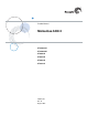
Product Manual Momentus 5400.2 ® ST9120821A ST9100824A ST98823A ST96812A ST94813A ST93811A 100367120 Rev.
©2004-2007, Seagate Technology LLC All rights reserved. Publication number: 100367120, Rev. B August 2007 Seagate, Seagate Technology and the Wave logo are registered trademarks of Seagate Technology LLC in the United States and/or other countries. Momentus, SeagateSeaBOARD, SeaFONE, SeaTDD, and SeaTools are either trademarks or registered trademarks of Seagate Technology LLC or one of its affiliated companies in the United States and/ or other countries.
Contents 1.0 Introduction. . . . . . . . . . . . . . . . . . . . . . . . . . . . . . . . . . . . . . . . . . . . . . . . . . . . . . . . . . . . . . . . . . . 1 2.0 Drive specifications . . . . . . . . . . . . . . . . . . . . . . . . . . . . . . . . . . . . . . . . . . . . . . . . . . . . . . . . . . . . 3 2.1 Specification summary . . . . . . . . . . . . . . . . . . . . . . . . . . . . . . . . . . . . . . . . . . . . . . . . . . . . 3 2.2 Formatted capacity . . . . . . . . . . . . . . . . . . . . . . .
ii Momentus 5400.2 PATA Product Manual, Rev.
List of Figures Figure 1. Figure 2. Figure 3. Figure 4. Momentus 5400.2 PATA disc drive . . . . . . . . . . . . . . . . . . . . . . . . . . . . . . . . . . . . . . . . . . . . . 1 Typical 5V startup and operation current profile . . . . . . . . . . . . . . . . . . . . . . . . . . . . . . . . . . . . 9 Jumper settings . . . . . . . . . . . . . . . . . . . . . . . . . . . . . . . . . . . . . . . . . . . . . . . . . . . . . . . . . . . 18 Mounting dimensions—top, side and end view . . . . . . . . . . . . . .
iv Momentus 5400.2 PATA Product Manual, Rev.
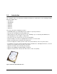
1.0 Introduction This manual describes the functional, mechanical and interface specifications for the following Seagate® Momentus®5400.2 drives: • ST9120821A • ST9100824A • ST98823A • ST96812A • ST94813A • ST93811A These drives provide the following key features: • 5,400-RPM spindle speed and 8-Mbyte buffer combine for superior performance. • Quiet operation. Fluid Dynamic Bearing (FDB) motor. • High instantaneous (burst) data transfer rates (up to 100 Mbytes per second) using Ultra DMA mode 5.
2 Momentus 5400.2 PATA Product Manual, Rev.
2.0 Drive specifications Unless otherwise noted, all specifications are measured under ambient conditions, at 25°C, and nominal power. For convenience, the phrases the drive and this drive are used throughout this manual to indicate ST9120821A, ST9100824A, ST98823A, ST96812A, ST94813A and ST93811A model drives. 2.1 Specification summary The specifications listed in this table are for quick reference. For details on specification measurement or definition, see the appropriate section of this manual.
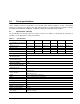
Table 1: Specifications Drive specification ST9120821A ST9100824A ST98823A Average seek time (msec typical) 12.5 Average seek, read (msec typical) 12.5 ST96812A ST94813A ST93811A Average seek, write (msec typical) 14.5 Full-stroke seek (msec) 22 (typical); 24 (max) Seek power (typical) 2.0 watts Read/write power (typical) Read: 1.8 watts; Write: 1.8 watts Idle mode (typical, low power) 0.80 watts Standby mode 0.26 watts (typical)** Sleep mode 0.
Table 1: Specifications Drive specification ST9120821A ST9100824A ST98823A ST96812A ST94813A ST93811A Service life 5 years Warranty 5 years on distribution units. To determine the warranty for a specific drive, use a web browser to access the following web page: www.seagate.com/support/service/ From this page, click on the “Verify Your Warranty” link. You will be asked to provide the drive serial number, model number (or part number) and country of purchase.
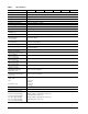
2.5 Recording and interface technology Technology Specification Interface Parallel ATA Recording method RLL 0,11 Recording density BPI (bits/inch typical) 778k Track density TPI (tracks/inch typical) 126k Areal density (Gbits/inch2 max) 98.2 Spindle speed (RPM) (± 0.2%) 5,400 Internal data-transfer rate OD (Mbytes/sec max) 42 I/O data-transfer rate (Mbytes/sec max) 100 (Ultra DMA mode 5) Interleave 1:1 Cache buffer 8 Mbytes (8,192 kbytes) 2.
2.7 Seek time Seek measurements are taken with nominal power at 25°C ambient temperature. All times are measured using drive diagnostics. The specifications below are defined as follows: • Track-to-track seek time is an average of all possible single-track seeks in both directions. • Average seek time is a true statistical random average of at least 5,000 measurements of seeks between random tracks, less overhead. Typical seek times (msec)* Read Write Track-to-track 1.0 1.5 Average 12.5 14.
2.9 Power specifications The drive receives DC power (+5V) through the interface connector. 2.9.1 Power consumption Power requirements for the drives are listed in the table on page 8. Typical power measurements are based on an average of drives tested, under nominal conditions, at 25°C ambient temperature. • Spinup power Spinup power is measured from the time of power-on to the time that the drive spindle reaches operating speed.
2.9.1.1 Typical current profile Figure 2. Typical 5V startup and operation current profile 2.9.2 Conducted noise Input noise ripple is measured at the host system power supply across an equivalent 15-ohm resistive load on the +5 volt line. Using 5-volt power, the drive is expected to operate with a maximum of 100 mV peak-to-peak square-wave injected noise at up to 10 MHz. Note. Equivalent resistance is calculated by dividing the nominal voltage by the typical RMS read/write current. 2.9.
2.9.4 Power-management modes The drive provides programmable power management to provide greater energy efficiency. In most systems, you can control power management through the system setup program.
2.10 Environmental specifications 2.10.1 Ambient temperature Ambient temperature is defined as the temperature of the environment immediately surrounding the drive. Actual drive case temperature should not exceed 65°C (149°F) within the operating ambient conditions. Above 1,000 feet (305 meters), the maximum temperature is derated linearly by 1°C every 1000 feet. Operating Nonoperating 2.10.
2.10.5 Shock All shock specifications assume that the drive is mounted securely with the input shock applied at the drive mounting screws. Shock may be applied in the X, Y or Z axis. 2.10.5.1 Operating shock These drives comply with the performance levels specified in this document when subjected to a maximum operating shock of 250 Gs based on half-sine shock pulses of 2 msec. Shocks should not be repeated more than two times per second. 2.10.5.
2.11 Acoustics Drive acoustics are measured as overall A-weighted acoustic sound power levels (no pure tones). All measurements are consistent with ISO document 7779. Sound power measurements are taken under essentially free-field conditions over a reflecting plane. For all tests, the drive is oriented with the cover facing upward. Note. For seek mode tests, the drive is placed in seek mode only. The number of seeks per second is defined by the following equation: (Number of seeks per second = 0.
2.13 Reliability Measurement type Specification Nonrecoverable read errors 1 per 1014 bits read, max. Annualized Failure Rate (AFR) 0.
Korean RRL If these drives have the Korea Ministry of Information and Communication (MIC) logo, they comply with paragraph 1 of Article 11 of the Electromagnetic Compatibility control Regulation and meet the Electromagnetic Compatibility (EMC) Framework requirements of the Radio Research Laboratory (RRL) Ministry of Information and Communication Republic of Korea. These drives have been tested and comply with the Electromagnetic Interference/Electromagnetic Susceptibility (EMI/EMS) for Class B products.
If necessary, you should consult your dealer or an experienced radio/television technician for additional suggestions. You may find helpful the following booklet prepared by the Federal Communications Commission: How to Identify and Resolve Radio-Television Interference Problems. This booklet is available from the Superintendent of Documents, U.S. Government Printing Office, Washington, DC 20402. Refer to publication number 004-000-00345-4. 2.
3.0 Configuring and mounting the drive This section contains the specifications and instructions for configuring and mounting the drive. 3.1 Handling and static discharge precautions After unpacking, and before installation, the drive may be exposed to potential handling and electrostatic discharge (ESD) hazards.
3.2 Jumper settings 3.2.1 Master/slave configuration Use the options jumper block shown in Figure 3 to configure the drive for operation. This jumper block is the 4-pin header adjacent to pins 1 and 2 of the I/O signal pins. For additional information about using the Cable select option, see Section 3.2.2. The “Master or single drive” option is the factory default setting. Drive is master (or single drive) Drive is slave Cable select Figure 3. Jumper settings 3.2.
3.3 Drive mounting You can mount the drive using four screws in the side-mounting holes or four screws in the bottom-mounting holes. See Figure 4 for drive mounting dimensions (dimensions in inches with mm in parentheses). Follow these important mounting precautions when mounting the drive: • Allow a minimum clearance of 0.030 inches (0.76 mm) around the entire perimeter of the drive for cooling. • Use only M3 x 0.5 mounting screws. • Do not overtighten the mounting screws (maximum torque: 4.0 inch-lb).
20 Momentus 5400.2 PATA Product Manual, Rev.
4.0 ATA interface These drives use the industry-standard ATA task file interface that supports 16-bit data transfers. It supports ATA programmed input/output (PIO) modes 0–4; multiword DMA modes 0–2, and Ultra DMA modes 0–5. The drive also supports the use of the IORDY signal to provide reliable high-speed data transfers.
4.1.1 Supported ATA commands The following table lists ATA-standard commands that the drive supports. For a detailed description of the ATA commands, refer to the Draft ATA-6 Standard...
Table 7: Supported commands Command name Command code (in hex) Security Unlock F2H Seek 70H Set Drive Parameters 91H Set Features EFH Set Max Address F9H Note: Individual Set Max commands are identified by the value placed in the Set Max Features register as defined to the right. Address Password Lock Unlock Freeze Lock Set Multiple Mode C6H Sleep 99H, E6H S.M.A.R.T.
Table 7: Supported commands Command name Command code (in hex) Security Freeze Lock F5H Security Disable Password F6H 24 Momentus 5400.2 PATA Product Manual, Rev.
4.1.2 Identify Device command The Identify Device command (command code ECH) transfers information about the drive to the host following power up. The data is organized as a single 512-byte block of data, whose contents are shown in Table 7 on page 22. All reserved bits or words should be set to zero. Parameters listed with an “x” are drive-specific or vary with the state of the drive. See Section 2.0 on page 3 for default parameter settings.
Word Description Value 57–58 Current capacity in sectors xxxxH 59 Number of sectors transferred during a Read Multiple or Write Multiple command xxxxH 60–61 Total number of user-addressable LBA sectors available (see Section 2.
Word Description Value 129–159 Seagate-reserved xxxxH 160–254 ATA-reserved 0000H 255 Integrity word xxA5H Note. See the bit descriptions below for words 63, 88, 93 and 94 of the Identify Drive data. Description (if bit is set to 1) Bit Word 63 0 Multiword DMA mode 0 is supported. 1 Multiword DMA mode 1 is supported. 2 Multiword DMA mode 2 is supported. 8 Multiword DMA mode 0 is currently active. 9 Multiword DMA mode 1 is currently active.
4.1.3 Set Features command This command controls the implementation of various features that the drive supports. When the drive receives this command, it sets BSY, checks the contents of the Features register, clears BSY and generates an interrupt. If the value in the register does not represent a feature that the drive supports, the command is aborted. Power-on default has the read look-ahead and write caching features enabled.
5.0 Compatibility summary 5.1 Installation considerations Many of today’s mobile computers have been designed to make it possible for the end user to replace the hard drive. Refer to your system’s user manual for the location of the hard drive compartment and the specific instructions regarding replacement. Refer to your system manufacturer’s support website for the most up-todate information. Read and follow all instructions regarding the proper steps to be taken when replacing the system hard drive.
System Compatibility Seagate Product Assurance has tested Momentus drives in the systems listed in Table 9. Testing included multiple BIOS versions and operating systems. This testing was done to demonstrate compatibility with various hardware and software configurations. Hardware and software combinations, other than those tested, may also be compatible with this drive.
5.2 BIOS versions tested The following list indicates the types of BIOS Seagate tested during the compatibility testing process. The list highlights the major BIOS manufacturers. Individual systems contain variations of these BIOS versions and were tested with regard to their implementation in the individual systems. Table 10: Vendor Tested BIOS versions Release Revision ACER 1.01 ACPI Ver. 1.20 AMI Various Apple 4.71F1 Apple 4.8.4F1 Award Various Various Compal 38118 v2.
5.3 Operating system versions tested This list indicates the types of Operating Systems Seagate tested during the compatibility testing process and highlights the major OS manufacturers. Several variations of the major operating systems have been tested. Table 11: Operating systems tested Manufacturer Version/Release Apple MacOS 9.22 Apple MacOS X 10.2.3 Microsoft MSDOS 6.
6.0 Seagate Technology support services Online services Internet www.seagate.com for information about Seagate products and services. Worldwide support is available 24 hours daily by e-mail for your questions. Presales Support: www.seagate.com/support/email/email_presales.html or Presales@Seagate.com Technical Support: www.seagate.com/support/email/email_disc_support.html or DiscSupport@Seagate.com mySeagate my.seagate.
Customer Service Operations Warranty Service Seagate offers worldwide customer support for Seagate drives. Seagate distributors, OEMs and other direct customers should contact their Seagate Customer Service Operations (CSO) representative for warrantyrelated issues. Resellers or end users of drive products should contact their place of purchase or one of the Seagate CSO warranty centers for assistance. Have your drive’s “ST” model number and serial number available.
European support services For presales and technical support in Europe, dial the Seagate Service Center toll-free number for your specific location. If your location is not listed here, dial our presales and technical support call center at +1-405324-4714 from 8:00 A.M. to 11:45 A.M. and 1:00 P.M. to 5:00 P.M. (Central Europe time) Monday through Friday. The presales and technical support call center is located in Oklahoma City, USA.
Asia/Pacific support services For Asia/Pacific presales and technical support, dial the toll-free number for your specific location. The Asia/ Pacific toll-free numbers are available from 6:00 A.M. to 10:45 A.M. and 12:00 P.M. to 6:00 P.M. (Australian Eastern time) Monday through Friday, except as noted. If your location is not listed here, direct dial one of our technical support locations. Warranty service is available from 9:00 A.M. to 6:00 P.M. April through October, and 10:00 A.M. to 7:00 P.M.
Publication feedback survey We are interested in your comments and suggestions regarding this publication. Please take a few minutes to participate in our survey at the following URL: http://survey.seagate.com/survey/techpubs.nsf Thank you for your time and comments. Momentus 5400.2 PATA Product Manual, Rev.
38 Momentus 5400.2 PATA Product Manual, Rev.
Index Numerics 3D Defense System 1 A acoustics 13 Active mode 10 AFR 14 agency certification (regulatory) 14 altitude 11 ambient conditions 3 ambient temperature 7, 11 Annualized Failure Rate 14 areal density 6 ATA interface 21 ATA-standard commands 22 Australian C-Tick 15 autodetection 1 average seek time 7 B BIOS manufacturers 31 BPI 6 buffer 1, 6 burst 1 C cable select 1 cable-select option 18 cache 1, 6 case temperature 11 CE mark 14 certification 14 Check Power Mode 23 chemical substances 16 command
I P I/O data-transfer rate 6 Identify Device 22 Identify Device command 25 Idle 8, 23 Idle and Standby timers 10 Idle Immediate 23 Idle mode 10 Idle mode power 8 IEC950 14 Information Technology Equipment 14 Initialize Device Parameters 22 interface 6, 21 interface signals 21 interference 15 interleave 6 internal data-transfer rate OD 6 ISO document 7779 13 physical characteristics 6 physical organization 5 pins 21 PIO 21 power consumption 8 power dissipation 8 power frequency h-field immunity 13 power m
security commands 23 Security Disable Password 24 Security Erase Prepare 23 Security Erase Unit 23 Security Freeze Lock 24 Security Set Password 23 Security Unlock 23 Seek 23 seek mode 8 seek time 7 Seeking 8 Self refresh, low power 10 Service Life 14 servo electronics 8 Set Features 23 Set Features command 28 Set Max 23 Set Multiple Mode 23 shock 12 signals 21 single-track seeks 7 Sleep 8, 23 Sleep mode 10 software utilities 32 sound 13 specifications 3 spindle speed 6 Spinup 8 spinup power 8 Standby 8, 23
42 Momentus 5400.2 PATA Product Manual, Rev.
Seagate Technology LLC 920 Disc Drive, Scotts Valley, California 95066-4544, USA Publication Number: 100367120, Rev. B, Printed in U.S.A.