Product Manual Momentus 5400.6 SATA ST9500325AS ST9500325ASG ST9400326AS ST9320325ASG ST9320325AS ST9250315ASG ST9250315AS ST9160314ASG ST9160314AS ST9120315ASG ST9160301AS ST980313ASG ST9120315AS ST980313AS 100528359 Rev.
Copyright © 2009 Seagate Technology LLC. All rights reserved. Printed in U.S.A. Publication number: 100528359, Rev. E, September 2009 Seagate, Seagate Technology and the Wave logo are registered trademarks of Seagate Technology LLC in the United States and/or other countries. Momentus, SeaTools and SeaTDD are either trademarks or registered trademarks of Seagate Technology LLC or one of its affiliated companies in the United States and/or other countries.
Contents 1.0 Introduction. . . . . . . . . . . . . . . . . . . . . . . . . . . . . . . . . . . . . . . . . . . . . . . . . . . . . . . . . . . . . . . . . . . 1 1.1 About the Serial ATA interface . . . . . . . . . . . . . . . . . . . . . . . . . . . . . . . . . . . . . . . . . . . . . . 2 2.0 Drive specifications . . . . . . . . . . . . . . . . . . . . . . . . . . . . . . . . . . . . . . . . . . . . . . . . . . . . . . . . . . . . 3 2.1 Specification summary table . . . . . . . . . . . . . . . . . . . .
ii Momentus 5400.6 SATA Product Manual, Rev.
List of Figures Figure 1. Figure 2. Figure 3. Figure 4. Typical +5V only startup and operation current profile . . . . . . . . . . . . . . . . . . . . . . . . . . . . . . Serial ATA connectors . . . . . . . . . . . . . . . . . . . . . . . . . . . . . . . . . . . . . . . . . . . . . . . . . . . . . . Attaching SATA cabling . . . . . . . . . . . . . . . . . . . . . . . . . . . . . . . . . . . . . . . . . . . . . . . . . . . . . Mounting dimensions—top, side and end view . . . . . . . . . . . . . . . . . . .
1.0 Introduction This manual describes the functional, mechanical and interface specifications for the following Seagate Momentus® 5400.6 SATA model drives: • • • • • • • • ST9500325AS ST9400326AS ST9320325AS ST9250315AS ST9160314AS ST9160301AS ST9120315AS ST980313AS • • • • • ST9500325ASG ST9320325ASG ST9250315ASG ST9160314ASG • ST9120315ASG • ST980313ASG These drives provide the following key features: • 5,400-RPM spindle speed. • 8-Mbyte buffer.
1.1 About the Serial ATA interface The Serial ATA interface provides several advantages over the traditional (parallel) ATA interface. The primary advantages include: • Easy installation and configuration with true plug-and-play connectivity. It is not normally necessary to set any jumpers or other configuration options. • Thinner and more flexible cabling for improved enclosure airflow and ease of installation. • Scalability to higher performance levels.
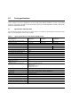
2.0 Drive specifications Unless otherwise noted, all specifications are measured under ambient conditions, at 25°C, and nominal power. For convenience, the phrases the drive and this drive are used throughout this manual to indicate the Momentus 5400.6 SATA models. 2.1 Specification summary table The specifications listed in this table are for quick reference. For details on specification measurement or definition, see the appropriate section of this manual. .
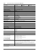
Table 1: Drive specifications for 500, 400 and 320 GB models Drive specification ST9500325AS ST9500325ASG Average seek, read (msec typical) 14 Full-stroke seek, read (msec max) 30 Startup current, +5V (max) 1 amp Seek power (typical) 1.54 watts ST9400326AS Read/write power (typical) Read: 1.40 watts; Write: 1.78 watts Idle mode, low power (typical) 0.67 watts Standby mode 0.20 watts (typical)*** Sleep mode 0.
Table 2: Drive specifications for 250 and 160 GB models Drive specification ST9250315AS ST9250315ASG ST9160314AS ST9160314ASG Formatted Gbytes (512 bytes/sector)* 250 160 Guaranteed sectors 488,397,168 312,581,808 Bytes per sector 512 Physical read/write heads 2 Discs 1 Cache (Mbytes) 8 Recording density in BPI (bits/inch avg) 1,490k ST9160301AS 1,238k Track density TPI (tracks/inch avg) 265k 210k Areal density (Gbits/inch2 avg) 394 269 Spindle speed (RPM) 5,400 Average latenc
Table 2: Drive specifications for 250 and 160 GB models Drive specification ST9250315AS ST9250315ASG ST9160314AS ST9160314ASG Altitude, nonoperating (meters below mean sea level, max) –304.8 m to 12,192 m (–1000 ft to 40,000+ ft) Shock, operating (Gs max at 2 msec) 350 Shock, nonoperating (Gs max at 2 msec) 800 Shock, nonoperating (Gs max at 1 msec) 1,000 Shock, nonoperating (Gs max at 0.5 msec) 600 Vibration, operating 1.0 G (0 to peak, 5–500 Hz) Vibration, nonoperating 5.
Table 3: Drive specifications for 120 and 80 GB models Drive specification ST9120315AS ST9120315ASG ST980313AS ST980313ASG Formatted Gbytes (512 bytes/sector)* 120 80 Guaranteed sectors 234,441,648 156,301,488 Bytes per sector 512 Physical read/write heads 1 Discs 1 Cache (Mbytes) 8 Recording density in BPI (bits/inch avg) 1,490k Track density TPI (tracks/inch avg) 265k Areal density (Gbits/inch2 avg) 394 Spindle speed (RPM) 5,400 Average latency (msec) 5.
Table 3: Drive specifications for 120 and 80 GB models Drive specification ST9120315AS ST9120315ASG ST980313AS ST980313ASG Shock, operating (Gs max at 2 msec) 350 Shock, nonoperating (Gs max at 2 msec) 800 Shock, nonoperating (Gs max at 1 msec) 1,000 Shock, nonoperating (Gs max at 0.5 msec) 600 Vibration, operating 1.0 G (0 to peak, 5–500 Hz) Vibration, nonoperating 5.0 Gs (0 to peak, 5–500 Hz) Drive acoustics, sound power (bels) Idle** 2.4 (typical) 2.6 (max) Performance seek 2.
2.2.1 LBA mode When addressing these drives in LBA mode, all blocks (sectors) are consecutively numbered from 0 to n–1, where n is the number of guaranteed sectors as defined above. See Section 4.3.1, "Identify Device command" (words 60-61 and 100-103) for additional information about 48bit addressing support of drives with capacities over 137 Gbytes. 2.
2.6 Physical characteristics Drive specification Height (mm) (inches) 9.5 +/-0.2 0.374 +/-0.0079 Width (mm) (inches) 69.85 +/-0.25 2.75 +/-0.0098 Length (mm) (inches) 100.35 +0.20 / -0.25 3.957 +0.0079 / -0.0098 Weight (max) ST9500325AS ST9500325ASG ST9400326AS ST9320325AS ST9320325ASG 2.7 98.8 grams 0.218 pounds ST9250315AS ST9250315ASG ST9160314AS ST9160314ASG ST9120315AS ST9120315ASG ST980313AS ST980313ASG 93.5 grams 0.206 pounds ST9160301AS 105 grams 0.
2.9 Power specifications The drive receives DC power (+5V) through a native SATA power connector. 2.9.1 Power consumption Power requirements for the drives are listed in the table on page 11. Typical power measurements are based on an average of drives tested, under nominal conditions, at 25°C ambient temperature. • Spinup power Spinup power is measured from the time of power-on to the time that the drive spindle reaches operating speed.
2.9.1.1 Typical current profile Figure 1. Typical +5V only startup and operation current profile 2.9.2 Deferred spinup Momentus 5400.6 SATA drives do not support the deferred spinup option. If you require this option, refer to the Momentus 5400.3 SATA Blade Server family of drives. 2.9.3 Conducted noise Input noise ripple is measured at the host system power supply across an equivalent 15-ohm resistive load on the +5 volt line.
2.9.5 Power-management modes The drive provides programmable power management to provide greater energy efficiency. In most systems, you can control power management through the system setup program.
2.10 Environmental specifications 2.10.1 Ambient temperature Ambient temperature is defined as the temperature of the environment immediately surrounding the drive. Actual drive case temperature should not exceed 70°C (158°F) within the operating ambient conditions. Above 1,000 feet (305 meters), the maximum temperature is derated linearly by 1°C every 1000 feet. Operating: 0° to 60°C (32° to 140°F) Nonoperating: –40° to 70°C (–40° to 158°F) 2.10.
2.10.5 Shock All shock specifications assume that the drive is mounted securely with the input shock applied at the drive mounting screws. Shock may be applied in the X, Y or Z axis. Note. Additional shock protection is provided by the Free Fall Protection feature on ST9500325ASG, ST9320325ASG, ST9250315ASG, ST9160314ASG, ST9120315ASG and ST980313ASG models. See Section 2.13.1 for additional information about this feature. 2.10.5.
2.11 Acoustics Drive emission of sound is measured consistent with the ECMA-74 and its’ referenced standards. Testing is conducted at room temperature (approximately 25°C). Emission levels are reported as the total A-weighted sound power levels for steady state, idle, and active seek modes of operation.
2.13 Reliability Measurement type Specification Nonrecoverable read errors 1 per 1014 bits read, max. Annualized Failure Rate (AFR) <0.
2.14 Agency certification 2.14.1 Safety certification The drives are recognized in accordance with UL 1950 and CSA C22.2 (950) and meet all applicable sections of IEC950 and EN 60950 as tested by TUV North America. 2.14.2 Electromagnetic compatibility Hard drives that display the CE mark comply with the European Union (EU) requirements specified in the Electromagnetic Compatibility Directive (89/336/EEC).
2.14.3 FCC verification These drives are intended to be contained solely within a personal computer or similar enclosure (not attached as an external device). As such, each drive is considered to be a subassembly even when it is individually marketed to the customer. As a subassembly, no Federal Communications Commission verification or certification of the device is required.
2.15 Environmental protection Seagate designs its products to meet environmental protection requirements worldwide, including regulations restricting certain chemical substances. 2.15.1 European Union Restriction of Hazardous Substances (RoHS) Seagate designs its products to meet environmental protection requirements worldwide, including regulations restricting certain chemical substances.
3.0 Configuring and mounting the drive This section contains the specifications and instructions for configuring and mounting the drive. 3.1 Handling and static-discharge precautions After unpacking, and before installation, the drive may be exposed to potential handling and electrostatic discharge (ESD) hazards.
3.2 Configuring the drive Each drive on the Serial ATA interface connects in a point-to-point configuration with the Serial ATA host adapter. There is no master/slave relationship because each drive is considered a master in a point-to-point relationships. If two drives are attached on one Serial ATA host adapter, the host operating system views the two devices as if they were both “masters” on two separate ports. This means both drives behave as if they are Device 0 (master) devices.
3.4 Drive mounting You can mount the drive using four screws in the side-mounting holes or four screws in the bottom-mounting holes. See Figure 4 for drive mounting dimensions. Follow these important mounting precautions when mounting the drive: • Allow a minimum clearance of 0.030 inches (0.76 mm) around the entire perimeter of the drive for cooling. • Use only M3 UNC mounting screws. • Do not overtighten the mounting screws. Maximum torque: 4.0 inch-lb (0.4519 N-m). • Four (4) threads (0.080 inches, 2.
Measurements shown in Figure 4 are in inches. Figure 4. Mounting dimensions—top, side and end view 24 Momentus 5400.6 SATA Product Manual, Rev.
4.0 Serial ATA (SATA) interface These drives use the industry-standard Serial ATA interface that supports FIS data transfers. It supports ATA programmed input/output (PIO) modes 0–4; multiword DMA modes 0–2, and Ultra DMA modes 0–6. The drive also supports the use of the IORDY signal to provide reliable high-speed data transfers. For detailed information about the Serial ATA interface, refer to the “Serial ATA: High Speed Serialized AT Attachment” specification. 4.
Table 9: Segment Power Serial ATA connector pin definitions Pin Function Definition P1 V33 3.3V power P2 V33 3.3V power P3 V33 3.
4.3 Supported ATA commands The following table lists Serial ATA standard commands that the drive supports. For a detailed description of the ATA commands, refer to the Serial ATA: High Speed Serialized AT Attachment specification. See “S.M.A.R.T. commands” on page 34.for details and subcommands used in the S.M.A.R.T. implementation.
Command name Command code (in hex) S.M.A.R.T. Enable/Disable Autosave B0h/D2h S.M.A.R.T. Enable Operations B0h/D8h S.M.A.R.T. Enable/Disable Auto Offline B0h/DBh S.M.A.R.T. Enable One Attribute Modification B0h/E0h S.M.A.R.T. Execute Offline B0h/D4h S.M.A.R.T. Read Attribute Thresholds B0h/D1h S.M.A.R.T. Read Data B0h/D0h S.M.A.R.T. Read Log Sector B0h/D5h S.M.A.R.T. Return Status B0h/DAh S.M.A.R.T. Save Attribute Values B0h/D3h S.M.A.R.T. Write Attribute Thresholds B0h/D7h S.M.A.R.
4.3.1 Identify Device command The Identify Device command (command code ECH) transfers information about the drive to the host following power up. The data is organized as a single 512-byte block of data, whose contents are shown in the table on page 27. All reserved bits or words should be set to zero. Parameters listed with an “x” are drive-specific or vary with the state of the drive. The following commands contain drive-specific features that may not be included in the Serial ATA specification.
Word Description Value 54 Number of current logical cylinders xxxxH 55 Number of current logical heads xxxxH 56 Number of current logical sectors per logical track xxxxH 57–58 Current capacity in sectors xxxxH 59 Number of sectors transferred during a Read Multiple or Write Multiple command xxxxH 60–61 Total number of user-addressable sectors This field contains a value that is one greater than the total number of user-addressable sectors.
Word Description Value 89 Security erase time 0000H 90 Enhanced security erase time 0000H 92 Master password revision code FFFEH 93 Hardware reset value (see description following this table) xxxxH 94 Auto acoustic management setting xxxxH 95–99 ATA-reserved 0000H 100– 103 Total number of user-addressable LBA sectors available (see Section 2.2 for related information) These words are required for drives that support the 48-bit addressing feature. Maximum value: 0000FFFFFFFFFFFFh.
32 Bit Word 88 0 Ultra DMA mode 0 is supported. 1 Ultra DMA mode 1 is supported. 2 Ultra DMA mode 2 is supported. 3 Ultra DMA mode 3 is supported. 4 Ultra DMA mode 4 is supported. 5 Ultra DMA mode 5 is supported 6 Ultra DMA mode 6 is supported 8 Ultra DMA mode 0 is currently active. 9 Ultra DMA mode 1 is currently active. 10 Ultra DMA mode 2 is currently active. 11 Ultra DMA mode 3 is currently active. 12 Ultra DMA mode 4 is currently active.
4.3.2 Set Features command This command controls the implementation of various features that the drive supports. When the drive receives this command, it sets BSY, checks the contents of the Features register, clears BSY and generates an interrupt. If the value in the register does not represent a feature that the drive supports, the command is aborted. Power-on default has the read look-ahead and write caching features enabled.
4.3.3 S.M.A.R.T. commands S.M.A.R.T. provides near-term failure prediction for disc drives. When S.M.A.R.T. is enabled, the drive monitors predetermined drive attributes that are susceptible to degradation over time. If self-monitoring determines that a failure is likely, S.M.A.R.T. makes a status report available to the host. Not all failures are predictable. S.M.A.R.T. predictability is limited to the attributes the drive can monitor. For more information on S.M.A.R.T.
5.0 Seagate Technology support services Internet For information regarding Seagate products and services, visit www.seagate.com. Worldwide support is available 24 hours daily by email for your questions. Presales Support: Presales@Seagate.com Technical Support: DiscSupport@Seagate.com Warranty Support: http://www.seagate.com/www/en-us/support/warranty_&_returns_assistance mySeagate my.seagate.com is the industry's first Web portal designed specifically for OEMs and distributors.
Customer Service Operations Warranty Service Seagate offers worldwide customer support for Seagate products. Seagate distributors, OEMs and other direct customers should contact their Seagate Customer Service Operations (CSO) representative for warrantyrelated issues. Resellers or end users of drive products should contact their place of purchase or Seagate warranty service for assistance. Have your serial number and model or part number available.
Index A ACA 18 acoustics 4, 6, 8, 16 Active mode 13 Address 27 AFR 17 Agency certification 18 Altitude 14 Altitude, nonoperating 4, 6, 7 Altitude, operating 4, 5, 7 Ambient temperature 4, 5, 7, 14 ambient temperature 10 Annualized Failure Rate 17 Annualized Failure Rate (AFR) 4, 6, 8 Areal density 3, 5, 7, 9 ATA commands 27 ATA data-transfer modes supported 3, 5, 7 Australia/New Zealand Standard AS/NZS3548 1995 18 Australian Communication Authority (ACA) 18 Australian C-Tick 18 Average seek time 10 Average
H handling 21 Handling precautions 21 heads 9 Height 3, 5, 7 height 10 Humidity 14 humidity 4, 5, 7 I I/O data-transfer rate 3, 5, 7, 9 Identify 27 Identify Device 27 Identify Device command 29 Idle 11, 28 Idle and Standby timers 13 Idle Immediate 28 Idle mode 4, 5, 7, 13 Idle mode power 11 IEC950 18 Information Technology Equipment (ITE) 18 Initialize Device Parameters 27 Input noise ripple 12 Interface 9 interface 25 Interleave 9 Internal data transfer rate 3, 5, 7 Internal data-transfer rate 9 ITE 18 K
read/write power and current 11 Recording density 3, 5, 7, 9 Recording method 9 Recording technology 9 Relative humidity 4, 5, 7, 14 Reliability 17 resistance 12 Retries 27 RF 16 RoHS 20 RPM 3, 5, 7 RRL 18 S S.M.A.R.T. 28 S.M.A.R.T.
40 Momentus 5400.6 SATA Product Manual, Rev.
Seagate Technology LLC 920 Disc Drive, Scotts Valley, California 95066-4544, USA Publication Number: 100528359, Rev.