Product Manual Momentus ® 7200-RPM 5400-RPM Standard models Free-fall sensor models ST9750423AS ST9750423ASG ST9750422AS ST9750420ASG ST9750420AS ST9640423ASG ST9750424AS * ST9500423ASG ST9640424AS ST9640423AS ST9640422AS * ST9500424AS ST9500423AS ST9500428AS * 100627937 Rev. C January 2011 * specifications for these models are available from Seagate technical support www.seagate.
Revision history Revision Rev. A Rev. B Rev. C Date 09/15/10 10/25/10 01/28/11 Sheets affected or comments Initial release. fc, 2, 4-9, 13-14, 16 & 26-28. Add Models to cover - ST9750424AS, ST9640422AS, ST9500428AS © 2011 Seagate Technology LLC. All rights reserved. Publication number: 100627937, Rev. C, January 2011 Seagate, Seagate Technology and the Wave logo are registered trademarks of Seagate Technology LLC in the United States and/or other countries.
Contents 1.0 Seagate Technology support services . . . . . . . . . . . . . . . . . . . . . . . . . . . . . . . . . . . . . . . . . . . . . 1 2.0 Introduction. . . . . . . . . . . . . . . . . . . . . . . . . . . . . . . . . . . . . . . . . . . . . . . . . . . . . . . . . . . . . . . . . . . 2 2.1 About the Serial ATA interface . . . . . . . . . . . . . . . . . . . . . . . . . . . . . . . . . . . . . . . . . . . . . . 3 3.0 Drive specifications . . . . . . . . . . . . . . . . . . . . . . . . . . . . . .
ii Momentus Product Manual, Rev.
List of Figures Figure 1. Figure 2. Figure 3. Figure 4. Figure 5. Typical +5V only startup and operation current profile (7200-RPM models) . . . . . . . . . . . . . Typical +5V only startup and operation current profile (5400-RPM models) . . . . . . . . . . . . . Serial ATA connectors . . . . . . . . . . . . . . . . . . . . . . . . . . . . . . . . . . . . . . . . . . . . . . . . . . . . . . Attaching SATA cabling . . . . . . . . . . . . . . . . . . . . . . . . . . . . . . . . . . . . . . . . . . . . . . .
1.0 Seagate Technology support services SEAGATE ONLINE SUPPORT and SERVICES For information regarding products and services, visit http://www.seagate.com/www/en-us/about/contact_us/ Available services include: Presales & Technical support Global Support Services telephone numbers & business hours Authorized Service Centers For information regarding Warranty Support, visit http://www.seagate.
2.
2.1 About the Serial ATA interface The Serial ATA interface provides several advantages over the traditional (parallel) ATA interface. The primary advantages include: • Easy installation and configuration with true plug-and-play connectivity. It is not normally necessary to set any jumpers or other configuration options. • Thinner and more flexible cabling for improved enclosure airflow and ease of installation. • Scalability to higher performance levels.
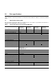
3.0 Drive specifications Unless otherwise noted, all specifications are measured under ambient conditions, at 25°C, and nominal power. 3.1 Specification summary table The specifications listed in this table are for quick reference. For details on specification measurement or definition, see the appropriate section of this manual.
Table 1: Drive specifications for 750, 640 and 500 GB models Drive specification ST9750423AS ST9750423ASG ST9640424AS ST9640423AS ST9640423ASG ST9750422AS ST9750420AS ST9750420ASG Write power (typical) 1.85W 2.4W Idle mode, low power (typical) 0.55W 0.70W Standby mode (typical) 0.15W *** Sleep mode (typical) 0.
3.2 Formatted capacity Model Formatted capacity* Guaranteed sectors ST9750423AS, ST9750423ASG, ST9750422AS, ST9750420AS and ST9750420ASG 750GB 1,465,149,168 ST9640424AS, ST9640423AS and ST9640423ASG 640GB 1,250,263,728 ST9500424AS, ST9500423AS and ST9500423ASG 500GB 976,773,168 Bytes per sector (logical) 512 *One Gbyte equals one billion bytes when referring to hard drive capacity. Accessible capacity may vary depending on operating environment and formatting. 3.2.
3.5 Recording and interface technology Interface Serial ATA (SATA) Recording method Perpendicular Recording density BPI (bits/in max) 1,586k Track density TPI (tracks/in max) 341k Areal density (Gb/in2 max) 541 Spindle speed (RPM) (± 0.2%) (ST9750423AS, ST9750423ASG, ST9640424AS, ST9640423AS and ST9640423ASG models only) 5400 Spindle speed (RPM) (± 0.
3.7 Seek time Seek measurements are taken with nominal power at 25°C ambient temperature. All times are measured using drive diagnostics. The specifications in the table below are defined as follows: • Track-to-track seek time is an average of all possible single-track seeks in both directions. • Average seek time is a true statistical random average of at least 5000 measurements of seeks between random tracks, less overhead. Table 2: Typical seek times Typical seek times (ms) Read Track-to-track 1.
3.9 Power specifications The drive receives DC power (+5V) through a native SATA power connector. 3.9.1 Power consumption Power requirements for the drives are listed in the table on page 9. Typical power measurements are based on an average of drives tested, under nominal conditions, at 25°C ambient temperature. • Spinup power Spinup power is measured from the time of power-on to the time that the drive spindle reaches operating speed.
3.9.1.1 Typical current profile Figure 1. Typical +5V only startup and operation current profile (7200-RPM models) Figure 2. Typical +5V only startup and operation current profile (5400-RPM models) 10 Momentus Product Manual, Rev.
3.9.2 Conducted noise Input noise ripple is measured at the host system power supply across an equivalent 15-ohm resistive load on the +5V line. Using 5V power, the drive is expected to operate with a maximum of 100mV peak-to-peak square-wave injected noise at up to 10 MHz. Note. Equivalent resistance is calculated by dividing the nominal voltage by the typical RMS read/write current. 3.9.3 Voltage tolerance Voltage tolerance (including noise): 5V ± 5% Momentus Product Manual, Rev.
3.9.4 Power-management modes The drive provides programmable power management to provide greater energy efficiency. In most systems, you can control power management through the system setup program.
3.10 Environmental specifications This section provides the temperature, humidity, shock, and vibration specifications for Momentus drives. 3.10.1 Ambient temperature Ambient temperature is defined as the temperature of the environment immediately surrounding the drive. Above 1000 feet (305 meters), the maximum temperature is derated linearly by 1°C every 1000 feet. Operating: 0°C to 60°C (32°F to 140°F) Nonoperating: –40°C to 70°C (–40°F to 158°F) 3.10.
3.10.6 Shock All shock specifications assume that the drive is mounted securely with the input shock applied at the drive mounting screws. Shock may be applied in the X, Y or Z axis. Note. Additional shock protection is provided by the Free Fall Protection feature on ST9750423ASG, ST9750420ASG, ST9640423ASG and ST9500423ASG models. See Section 3.13.1 for additional information about this feature. 3.10.6.
3.11 Acoustics Drive emission of sound is measured consistent with the ECMA-74 and its referenced standards. Testing is conducted at room temperature (approximately 25°C). Emission levels are reported as the total A-weighted sound power levers for steady state, idle, and active seeks modes of operation. Table 5: Drive A-weighted Sound Power Levels (SWL, BA) Idle* Performance seek 2.3 bels (typ) 2.5 bels (max) 2.6 bels (typ) 2.
3.13 Reliability Measurement type Specification Nonrecoverable read errors 1 per 1014 bits read, max. Annualized Failure Rate (AFR) 0.
Korean RRL If these drives have the Korean Communications Commission (KCC) logo, they comply with paragraph 1 of Article 11 of the Electromagnetic Compatibility control Regulation and meet the Electromagnetic Compatibility (EMC) Framework requirements of the Radio Research Laboratory (RRL) Communications Commission, Republic of Korea. These drives have been tested and comply with the Electromagnetic Interference/Electromagnetic Susceptibility (EMI/EMS) for Class B products.
3.15 Environmental protection Seagate designs its products to meet environmental protection requirements worldwide, including regulations restricting certain chemical substances. 3.15.1 European Union Restriction of Hazardous Substances (RoHS) Seagate designs its products to meet environmental protection requirements worldwide, including regulations restricting certain chemical substances.
4.0 Configuring and mounting the drive This section contains the specifications and instructions for configuring and mounting the drive. 4.1 Handling and static-discharge precautions After unpacking, and before installation, the drive may be exposed to potential handling and electrostatic discharge (ESD) hazards.
4.2 Configuring the drive Each drive on the Serial ATA interface connects in a point-to-point configuration with the Serial ATA host adapter. There is no master/slave relationship because each drive is considered a master in a point-to-point relationships. If two drives are attached on one Serial ATA host adapter, the host operating system views the two devices as if they were both “masters” on two separate ports. This means both drives behave as if they are Device 0 (master) devices.
4.4 Drive mounting You can mount the drive using four screws in the side-mounting holes or four screws in the bottom-mounting holes. See Figure 5 for drive mounting dimensions. Follow these important mounting precautions when mounting the drive: • Allow a minimum clearance of 0.030 inches (0.76 mm) around the entire perimeter of the drive for cooling. • Use only M3 UNC mounting screws. • Do not overtighten the mounting screws (maximum torque: 4.0 inch-lb). • Four (4) threads (0.
5.0 Serial ATA (SATA) interface These drives use the industry-standard Serial ATA interface that supports FIS data transfers. It supports ATA programmed input/output (PIO) modes 0–4; multiword DMA modes 0–2, and Ultra DMA modes 0–6. The drive also supports the use of the IORDY signal to provide reliable high-speed data transfers. For detailed information about the Serial ATA interface, refer to the “Serial ATA: High Speed Serialized AT Attachment” specification. 5.
5.2 Serial ATA device plug connector pin definitions Table 7 summarizes the signals on the Serial ATA interface and power connectors. Table 7: Segment Signal Serial ATA connector pin definitions Pin Function Definition S1 Ground 2nd mate S2 A+ Differential signal pair A from Phy S3 A- S4 Ground 2nd mate S5 B- Differential signal pair B from Phy S6 B+ S7 Ground 2nd mate Key and spacing separate signal and power segments Power P1 V33 3.3V power P2 V33 3.3V power P3 V33 3.
5.3 Supported ATA commands The following table lists Serial ATA standard commands that the drive supports. For a detailed description of the ATA commands, refer to the Serial ATA: High Speed Serialized AT Attachment specification. See “S.M.A.R.T. commands” on page 31.for details and subcommands used in the S.M.A.R.T. implementation.
Command name Command code (in hex) S.M.A.R.T. Enable/Disable Autosave B0h/D2h S.M.A.R.T. Enable Operations B0h/D8h S.M.A.R.T. Enable/Disable Auto Offline B0h/DBh S.M.A.R.T. Enable One Attribute Modification B0h/E0h S.M.A.R.T. Execute Offline B0h/D4h S.M.A.R.T. Free Fall Protection Host Interface FEh S.M.A.R.T. Read Attribute Thresholds B0h/D1h S.M.A.R.T. Read Data B0h/D0h S.M.A.R.T. Read Log Sector B0h/D5h S.M.A.R.T. Return Status B0h/DAh S.M.A.R.T. Save Attribute Values B0h/D3h S.M.
5.3.1 Identify Device command The Identify Device command (command code ECH) transfers information about the drive to the host following power up. The data is organized as a single 512-byte block of data, whose contents are shown in the table on page 27. All reserved bits or words should be set to zero. Parameters listed with an “x” are drive-specific or vary with the state of the drive. See Section 3.0 on page 4 for default parameter settings.
Word Description Value 54 Number of current logical cylinders xxxxH 55 Number of current logical heads xxxxH 56 Number of current logical sectors per logical track xxxxH 57–58 Current capacity in sectors xxxxH 59 Number of sectors transferred during a Read Multiple or Write Multiple command xxxxH 60–61 Total number of user-addressable sectors This field contains a value that is one greater than the total number of user-addressable sectors.
Word Description Value 89 Security erase time 0045H 90 Enhanced security erase time 0045H 91 Current APM values 8080H 92 Master password revision code FFFEH 93 Hardware reset value (see description following this table) xxxxH 94 Auto acoustic management setting xxxxH 95 Stream Min.
Note. See the bit descriptions below for words 63, 88, 93 and 94 of the Identify Drive data: Description (if bit is set to 1) Bit Word 63 0 Multiword DMA mode 0 is supported. 1 Multiword DMA mode 1 is supported. 2 Multiword DMA mode 2 is supported. 8 Multiword DMA mode 0 is currently active. 9 Multiword DMA mode 1 is currently active. 10 Multiword DMA mode 2 is currently active. Bit Word 88 0 Ultra DMA mode 0 is supported. 1 Ultra DMA mode 1 is supported.
5.3.2 Set Features command This command controls the implementation of various features that the drive supports. When the drive receives this command, it sets BSY, checks the contents of the Features register, clears BSY and generates an interrupt. If the value in the register does not represent a feature that the drive supports, the command is aborted. Power-on default has the read look-ahead and write caching features enabled.
5.3.3 S.M.A.R.T. commands S.M.A.R.T. provides near-term failure prediction for disc drives. When S.M.A.R.T. is enabled, the drive monitors predetermined drive attributes that are susceptible to degradation over time. If self-monitoring determines that a failure is likely, S.M.A.R.T. makes a status report available to the host. Not all failures are predictable. S.M.A.R.T. predictability is limited to the attributes the drive can monitor. For more information on S.M.A.R.T.
32 Momentus Product Manual, Rev.
Index A ACA 17 acoustics 5, 15 Active mode 12 Address 24 AFR 16 Agency certification 16 Altitude 13 Altitude, nonoperating 5 Altitude, operating 5 Ambient temperature 5, 13 ambient temperature 8 Annualized Failure Rate 16 Annualized Failure Rate (AFR) 5 Areal density 4, 7 ATA commands 24 ATA data-transfer modes supported 4 Australia/New Zealand Standard AS/NZS3548 1995 17 Australian Communication Authority (ACA) 17 Australian C-Tick 17 Average seek time 8 Average seek, read 4 B bels 5 BPI 4 buffer 4, 7 Byt
gradient 5 Guaranteed sectors 4, 6 guaranteed sectors 6 mounting the drive 19 H noise 11 nominal power 8 Nonoperating shock 14 Nonoperating vibration 14 Nonrecoverable read errors 5 nonrecoverable read errors 16 handling 19 Handling precautions 19 heads 6 Height 4 height 7 humidity 5 I I/O data-transfer rate 4, 7 Identify 24 Identify Device 24 Identify Device command 26 Idle 9, 25 Idle and Standby timers 12 Idle Immediate 25 Idle mode 5, 12 Idle mode power 9 IEC950 16 Information Technology Equipment (
Read Verify Sectors Extended 24 Read Verify Sectors without Retries 24 Read/write heads 6 Read/write power 4 read/write power and current 9 Recording density 4, 7 Recording method 7 Recording technology 7 Relative humidity 5, 13 Reliability 16 resistance 11 Retries 24 RF 15 RoHS 18 RPM 4 RRL 17 S S.M.A.R.T. 25 S.M.A.R.T.
36 Momentus Product Manual, Rev.
Seagate Technology LLC 920 Disc Drive, Scotts Valley, California 95066-4544, USA Publication Number: 100627937, Rev.