Product Manual Momentus XT ® ST95005620AS ST93205620AS ST92505610AS 100610268 Rev.
Revision history Revision Rev. A Date 03/25/10 Sheets affected or comments Initial release. © 2010 Seagate Technology LLC. All rights reserved. Publication number: 100610268, Rev. A, March 2010 Seagate, Seagate Technology and the Wave logo are registered trademarks of Seagate Technology LLC in the United States and/or other countries.
Contents 1.0 Introduction. . . . . . . . . . . . . . . . . . . . . . . . . . . . . . . . . . . . . . . . . . . . . . . . . . . . . . . . . . . . . . . . . . . 1 1.1 About the Serial ATA interface . . . . . . . . . . . . . . . . . . . . . . . . . . . . . . . . . . . . . . . . . . . . . . 2 2.0 Drive specifications . . . . . . . . . . . . . . . . . . . . . . . . . . . . . . . . . . . . . . . . . . . . . . . . . . . . . . . . . . . . 3 2.1 Specification summary table . . . . . . . . . . . . . . . . . . . .
ii Momentus XT Product Manual, Rev.
List of Figures Figure 1. Figure 2. Figure 3. Figure 4. Typical +5V only startup and operation current profile . . . . . . . . . . . . . . . . . . . . . . . . . . . . . . . 9 Serial ATA connectors . . . . . . . . . . . . . . . . . . . . . . . . . . . . . . . . . . . . . . . . . . . . . . . . . . . . . . 20 Attaching SATA cabling . . . . . . . . . . . . . . . . . . . . . . . . . . . . . . . . . . . . . . . . . . . . . . . . . . . . . 20 Mounting dimensions—top, side and end view . . . . . . . . . . . . . .
1.0 Introduction This manual describes the functional, mechanical and interface specifications for the following Seagate Momentus® XT model drives: Standard models ST95005620AS ST93205620AS ST92505610AS These drives provide the following key features: • 7200-RPM spindle speed. • 32MB buffer. • Quiet operation. Fluid Dynamic Bearing (FDB) motor. • High instantaneous (burst) data-transfer rates (up to 3Gbs). • Perpendicular recording technology.
1.1 About the Serial ATA interface The Serial ATA interface provides several advantages over the traditional (parallel) ATA interface. The primary advantages include: • Easy installation and configuration with true plug-and-play connectivity. It is not normally necessary to set any jumpers or other configuration options. • Thinner and more flexible cabling for improved enclosure airflow and ease of installation. • Scalability to higher performance levels.
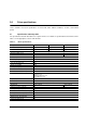
2.0 Drive specifications Unless otherwise noted, all specifications are measured under ambient conditions, at 25°C, and nominal power. 2.1 Specification summary table The specifications listed in this table are for quick reference. For details on specification measurement or definition, see the appropriate section of this manual.
Table 1: Drive specifications Drive specification ST95005620AS Read power (watts typical) 2.4 Write power (watts typical) 2.3 Idle mode, low power (watts typical) 0.8 Standby mode (watts typical) 0.40 *** ST93205620AS Sleep mode (watts typical) 0.
2.2 Formatted capacity Model Formatted capacity* Guaranteed sectors Bytes per sector ST95005620AS 500GB 976,773,168 512 ST93205620AS 320GB 625,142,448 512 ST92505610AS 250GB 488,397,168 512 *One GB equals one billion bytes when referring to hard drive capacity. Accessible capacity may vary depending on operating environment and formatting. 2.2.
2.4 Physical organization Drive model Read/write heads ST95005620AS 4 ST93205620AS 3 ST92505610AS 2 Number of discs 2 2.5 1 Recording and interface technology Interface Serial ATA (SATA) Recording method Perpendicular Recording density BPI (bits/in max) 1,490k Track density TPI (tracks/in max) 265k Areal density (Gb/in2 max) 394 Spindle speed (RPM) (± 0.2%) 7200 Maximum Internal transfer rate (Gb/s) 1.23 I/O data-transfer rate (Gb/s max) 3.
2.7 Seek time Seek measurements are taken with nominal power at 25°C ambient temperature. All times are measured using drive diagnostics. The specifications in the table below are defined as follows: • Track-to-track seek time is an average of all possible single-track seeks in both directions. • Average seek time is a true statistical random average of at least 5000 measurements of seeks between random tracks, less overhead. Table 2: Typical seek times Typical seek times (ms) Read Track-to-track 1.
2.9 Power specifications The drive receives DC power (+5V) through a native SATA power connector. 2.9.1 Power consumption Power requirements for the drives are listed in the table on page 8. Typical power measurements are based on an average of drives tested, under nominal conditions, at 25°C ambient temperature. • Spinup power Spinup power is measured from the time of power-on to the time that the drive spindle reaches operating speed.
2.9.1.1 Typical current profile Figure 1. Typical +5V only startup and operation current profile Momentus XT Product Manual, Rev.
2.9.2 Conducted noise Input noise ripple is measured at the host system power supply across an equivalent 15-ohm resistive load on the +5V line. Using 5V power, the drive is expected to operate with a maximum of 100mV peak-to-peak square-wave injected noise at up to 10 MHz. Note. Equivalent resistance is calculated by dividing the nominal voltage by the typical RMS read/write current. 2.9.3 Voltage tolerance Voltage tolerance (including noise): 5V ± 5% 10 Momentus XT Product Manual, Rev.
2.9.4 Power-management modes The drive provides programmable power management to provide greater energy efficiency. In most systems, you can control power management through the system setup program.
2.10 Environmental specifications This section provides the temperature, humidity, shock, and vibration specifications for Momentus XT drives. 2.10.1 Ambient temperature Ambient temperature is defined as the temperature of the environment immediately surrounding the drive. Actual drive case temperature should not exceed 65°C (149°F) within the operating ambient conditions. Above 1000 feet (305 meters), the maximum temperature is derated linearly by 1°C every 1000 feet.
2.10.6 Shock All shock specifications assume that the drive is mounted securely with the input shock applied at the drive mounting screws. Shock may be applied in the X, Y or Z axis. 2.10.6.1 Operating shock These drives comply with the performance levels specified in this document when subjected to a maximum operating shock of 350 Gs based on half-sine shock pulses of 2 ms. Shocks should not be repeated more than one time per axis. 2.10.6.
*During periods of drive idle, some offline activity may occur according to the S.M.A.R.T. specification, which may increase acoustic and power to operational levels. Test for Prominent Discrete Tones (PDTs) Seagate follows the ECMA-74 standards for measurement and identification of PDTs. An exception to this process is the use of the absolute threshold of hearing.
2.14 Agency certification 2.14.1 Safety certification The drives are recognized in accordance with UL 60950-1 and CSA C22.2 (950) and meet all applicable sections of IEC 60950-1 and EN60950-1 as tested by TUV North America. 2.14.2 Electromagnetic compatibility Hard drives that display the CE mark comply with the European Union (EU) requirements specified in the Electromagnetic Compatibility Directive (89/336/EEC).
This equipment is designed to provide reasonable protection against such interference in a residential installation. However, there is no guarantee that interference will not occur in a particular installation. If this equipment does cause interference to radio or television, which can be determined by turning the equipment on and off, you are encouraged to try one or more of the following corrective measures: • Reorient the receiving antenna. • Move the device to one side or the other of the radio or TV.
2.15 Environmental protection Seagate designs its products to meet environmental protection requirements worldwide, including regulations restricting certain chemical substances. 2.15.1 European Union Restriction of Hazardous Substances (RoHS) Seagate designs its products to meet environmental protection requirements worldwide, including regulations restricting certain chemical substances.
2.16 Corrosive environment Seagate electronic drive components pass accelerated corrosion testing equivalent to 10 years exposure to light industrial environments containing sulfurous gases, chlorine and nitric oxide, classes G and H per ASTM B845. However, this accelerated testing cannot duplicate every potential application environment.
3.0 Configuring and mounting the drive This section contains the specifications and instructions for configuring and mounting the drive. 3.1 Handling and static-discharge precautions After unpacking, and before installation, the drive may be exposed to potential handling and electrostatic discharge (ESD) hazards.
3.2 Configuring the drive Each drive on the Serial ATA interface connects in a point-to-point configuration with the Serial ATA host adapter. There is no master/slave relationship because each drive is considered a master in a point-to-point relationships. If two drives are attached on one Serial ATA host adapter, the host operating system views the two devices as if they were both “masters” on two separate ports. This means both drives behave as if they are Device 0 (master) devices.
3.4 Drive mounting You can mount the drive using four screws in the side-mounting holes or four screws in the bottom-mounting holes. See Figure 4 for drive mounting dimensions. Follow these important mounting precautions when mounting the drive: • Allow a minimum clearance of 0.030 inches (0.76 mm) around the entire perimeter of the drive for cooling. • Use only M3 UNC mounting screws. • Do not overtighten the mounting screws (maximum torque: 4.0 inch-lb). • Four (4) threads (0.
4.0 Serial ATA (SATA) interface These drives use the industry-standard Serial ATA interface that supports FIS data transfers. It supports ATA programmed input/output (PIO) modes 0–4; multiword DMA modes 0–2, and Ultra DMA modes 0–6. The drive also supports the use of the IORDY signal to provide reliable high-speed data transfers. For detailed information about the Serial ATA interface, refer to the “Serial ATA: High Speed Serialized AT Attachment” specification. 4.
4.2 Serial ATA device plug connector pin definitions Table 7 summarizes the signals on the Serial ATA interface and power connectors.. Table 7: Segment Signal Serial ATA connector pin definitions Pin Function Definition S1 Ground 2nd mate S2 A+ Differential signal pair A from Phy S3 A- S4 Ground 2nd mate S5 B- Differential signal pair B from Phy S6 B+ S7 Ground 2nd mate Key and spacing separate signal and power segments Power P1 V33 3.3V power P2 V33 3.3V power P3 V33 3.
4.3 Supported ATA commands The following table lists Serial ATA standard commands that the drive supports. For a detailed description of the ATA commands, refer to the Serial ATA: High Speed Serialized AT Attachment specification. See “S.M.A.R.T. commands” on page 30.for details and subcommands used in the S.M.A.R.T. implementation.
ATA-standard commands names Command code (in hex) S.M.A.R.T. Enable/Disable Autosave B0h/D2h S.M.A.R.T. Enable Operations B0h/D8h S.M.A.R.T. Enable/Disable Auto Offline B0h/DBh S.M.A.R.T. Enable One Attribute Modification B0h/E0h S.M.A.R.T. Execute Offline B0h/D4h S.M.A.R.T. Free Fall Protection Host Interface FEh S.M.A.R.T. Read Attribute Thresholds B0h/D1h S.M.A.R.T. Read Data B0h/D0h S.M.A.R.T. Read Log Sector B0h/D5h S.M.A.R.T. Return Status B0h/DAh S.M.A.R.T.
4.3.1 Identify Device command The Identify Device command (command code ECH) transfers information about the drive to the host following power up. The data is organized as a single 512-byte block of data, whose contents are shown in the table on page 27. All reserved bits or words should be set to zero. Parameters listed with an “x” are drive-specific or vary with the state of the drive. See Section 2.0 on page 3 for default parameter settings.
Word Description Value 59 Number of sectors transferred during a Read Multiple or Write Multiple command xxxxH 60–61 Total number of user-addressable sectors This field contains a value that is one greater than the total number of user-addressable sectors. The maximum value that shall be placed in this field is 0FFFFFFFh. The 0FFFFFFFh value applies to all capacities over 137GB (see Section 2.2 and 2.3 for related information).
Word Description Value 100–103 Total number of user-addressable LBA sectors available (see Section 2.2 for related information) These words are required for drives that support the 48-bit addressing feature. Maximum value: 0000FFFFFFFFFFFFh.
4.3.2 Bit Word 93 13 1 = 80-conductor cable detected, CBLID above VIH 0 = 40-conductor cable detected, CBLID below VIL Set Features command This command controls the implementation of various features that the drive supports. When the drive receives this command, it sets BSY, checks the contents of the Features register, clears BSY and generates an interrupt. If the value in the register does not represent a feature that the drive supports, the command is aborted.
4.3.3 S.M.A.R.T. commands S.M.A.R.T. provides near-term failure prediction for disc drives. When S.M.A.R.T. is enabled, the drive monitors predetermined drive attributes that are susceptible to degradation over time. If self-monitoring determines that a failure is likely, S.M.A.R.T. makes a status report available to the host. Not all failures are predictable. S.M.A.R.T. predictability is limited to the attributes the drive can monitor. For more information on S.M.A.R.T.
5.0 Seagate Technology support services Web For information regarding Seagate products and services, visit www.seagate.com. Worldwide support is available 24 hours daily by email for your questions. . Warranty Support: http://www.seagate.com/www/en-us/support/warranty_&_returns_assistance direct.seagate.com direct.seagate.com is the industry's first Web portal designed specifically for OEMs and distributors.
Customer Service Operations Presales Support Our Presales Support staff can help you determine which Seagate products are best suited for your specific application or computer system, as well as product availability and compatibility. Technical Support Seagate technical support is available to assist you online at support.seagate.com or through one of our call centers. Have your system configuration information and your "ST" model/product number available.
Index A ACA 15 acoustics 4, 13 Active mode 11 Address 24 AFR 14 Agency certification 15 Altitude 12 Altitude, nonoperating 4 Altitude, operating 4 Ambient temperature 4, 12 ambient temperature 7 Annualized Failure Rate 14 Annualized Failure Rate (AFR) 4 Areal density 3, 6 ATA commands 24 ATA data-transfer modes supported 3 Australia/New Zealand Standard AS/NZS3548 1995 15 Australian Communication Authority (ACA) 15 Australian C-Tick 15 Average seek time 7 Average seek, read 3 B bels 4 BPI 3 buffer 3, 6 Byt
H handling 19 Handling precautions 19 heads 5 Height 3 height 6 humidity 4 I I/O data-transfer rate 3, 6 Identify 24 Identify Device 24 Identify Device command 26 Idle 8, 25 Idle and Standby timers 11 Idle Immediate 25 Idle mode 4, 11 Idle mode power 8 IEC950 15 Information Technology Equipment (ITE) 15 Initialize Device Parameters 24 Input noise ripple 10 Interface 6 interface 22 Interleave 6 Internal data transfer rate 3 Internal data-transfer rate 6 ITE 15 K Korean RRL 15 L latency 3 LBA mode 5 Length
read/write power and current 8 Recording density 3, 6 Recording method 6 Recording technology 6 Relative humidity 4, 12 Reliability 14 resistance 10 Retries 24 RF 14 RoHS 17 RPM 3 RRL 15 S S.M.A.R.T. 25 S.M.A.R.T.
36 Momentus XT Product Manual, Rev.
Seagate Technology LLC 920 Disc Drive, Scotts Valley, California 95066-4544, USA Publication Number: 100610268, Rev.