Product Manual Constellation® ES.3 Serial ATA Standard models SED-ISE* Models ST4000NM0033 ST4000NM0103 ST3000NM0033 ST3000NM0103 ST2000NM0033 ST2000NM0103 ST1000NM0033 ST1000NM0103 * Instant Secure Erase Self-Encrypting drive models ST4000NM0053 ST3000NM0053 ST2000NM0053 ST1000NM0053 100671511 Rev.
Document Revision History Revision Rev. A Date 10/05/2011 Description of changes Initial release. © 2012 Seagate Technology LLC. All rights reserved. Publication number: 100671511, Rev. A October 2012 Seagate, Seagate Technology and the Wave logo are registered trademarks of Seagate Technology LLC in the United States and/or other countries.
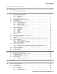
Contents Seagate® Technology Support Services . . . . . . . . . . . . . . . . . . . . . . . . . . . . . . . . . . . . . . . . . . . . . . . . . 1 1.0 Introduction. . . . . . . . . . . . . . . . . . . . . . . . . . . . . . . . . . . . . . . . . . . . . . . . . . . . . . . . . . . . . . . . . . . 3 1.1 About the Serial ATA interface . . . . . . . . . . . . . . . . . . . . . . . . . . . . . . . . . . . . . . . . . . . . . . 4 2.0 Drive specifications . . . . . . . . . . . . . . . . . . . . . . . . . . . . .
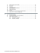
5.3 5.4 5.5 5.6 5.7 5.8 5.9 5.10 5.11 5.12 6.0 Random number generator (RNG). . . . . . . . . . . . . . . . . . . . . . . . . . . . . . . . . . . . . . . . . . . Drive locking . . . . . . . . . . . . . . . . . . . . . . . . . . . . . . . . . . . . . . . . . . . . . . . . . . . . . . . . . . . Data bands . . . . . . . . . . . . . . . . . . . . . . . . . . . . . . . . . . . . . . . . . . . . . . . . . . . . . . . . . . . . Cryptographic erase . . . . . . . . . . . . . . . . . . . . . . . . . . . . . . . . .
Seagate® Technology Support Services For information regarding online support and services, visit http://www.seagate.com/www/en-us/about/contact_us/ Available services include: • Presales & Technical support • Global Support Services telephone numbers & business hours • Authorized Service Centers For information regarding Warranty Support, visit http://www.seagate.com/support/warranty-and-returns/ For information regarding data recovery services, visit http://www.seagate.
2 Constellation ES.3 Serial ATA Product Manual, Rev.
1.0 INTRODUCTION This manual describes the functional, mechanical and interface specifications for the following Seagate Constellation® ES.3 Serial ATA model drives:. 1.
1.1 ABOUT THE SERIAL ATA INTERFACE The Serial ATA interface provides several advantages over the traditional (parallel) ATA interface. The primary advantages include: • Easy installation and configuration with true plug-and-play connectivity. It is not necessary to set any jumpers or other configuration options. • Thinner and more flexible cabling for improved enclosure airflow and ease of installation. • Scalability to higher performance levels.
2.0 DRIVE SPECIFICATIONS Unless otherwise noted, all specifications are measured under ambient conditions, at 25°C, and nominal power.
Drive specification ST4000NM0033 ST4000NM0053 ST4000NM0103 Relative humidity 5% to 90% (operating) 5% to 95% (nonoperating) Relative humidity gradient 30% per hour max Altitude, operating –304.8 m to 3,048 m (–1000 ft to 10,000+ ft) Altitude, nonoperating (below mean sea level, max) –304.
2.2 FORMATTED CAPACITY Formatted capacity* Guaranteed sectors 4TB 7,814.037,168 3TB 5,860,533,168 2TB 3,907,029,168 1TB 1,953,525,168 Bytes per sector 512 *One GB equals one billion bytes when referring to hard drive capacity. Accessible capacity may vary depending on operating environment and formatting. 2.2.1 LBA mode When addressing these drives in LBA mode, all blocks (sectors) are consecutively numbered from 0 to n–1, where n is the number of guaranteed sectors as defined above.
2.6 POWER SPECIFICATIONS The drive receives DC power (+5V or +12V) through a native SATA power connector. See Figure 10 on page 26. 2.6.1 Power consumption Power requirements for the drives are listed in the table on page 9. Typical power measurements are based on an average of drives tested, under nominal conditions, using 5.0V and 12.0V input voltage at 25°C ambient temperature.
Table 2 4TB Drive DC power requirements Notes Voltage 6.0Gb mode +5V Regulation +12V ± 5% Avg Idle Current * 0.28 0.50 Idle_A 0.17 0.49 Idle_B 0.16 0.45 Idle_C 0.15 0.27 Standby 0.15 0.01 Advanced Idle Current * Maximum Start Current DC (peak DC) 3σ 0.52 2.16 AC (Peak DC) 3σ 0.85 2.89 3σ 0.16 0.01 0.31 0.81 Delayed Motor Start (DC max) Peak operating current (random read): Typical DC Maximum DC 3σ 0.32 0.84 Maximum DC(peak) 3σ 1.83 2.43 0.30 0.
Table 3 3TB Drive DC power requirements Notes Voltage 6.0Gb mode +5V Regulation +12V ± 5% Avg Idle Current * 0.28 0.50 Idle_A 0.17 0.49 Idle_B 0.16 0.45 Idle_C 0.15 0.27 Standby 0.15 0.01 Advanced Idle Current * Maximum Start Current DC (peak DC) 3σ 0.52 2.16 AC (Peak DC) 3σ 0.85 2.89 3σ 0.16 0.01 0.31 0.81 Delayed Motor Start (DC max) Peak operating current (random read): Typical DC Maximum DC 3σ 0.32 0.84 Maximum DC(peak) 3σ 1.83 2.43 0.30 0.
Table 4 2TB Drive DC power requirements Notes Voltage 6.0Gb mode +5V Regulation +12V ± 5% Avg Idle Current * 0.28 0.36 Idle_A 0.17 0.36 Idle_B 0.16 0.32 Idle_C 0.15 0.21 Standby 0.15 0.01 Advanced Idle Current * Maximum Start Current DC (peak DC) 3σ 0.48 2.86 AC (Peak DC) 3σ 0.67 2.91 3σ 0.16 0.01 0.30 0.66 Delayed Motor Start (DC max) Peak operating current (random read): Typical DC Maximum DC 3σ 0.31 0.71 Maximum DC(peak) 3σ 1.40 2.27 0.30 0.
Table 5 1TB Drive DC power requirements Notes Voltage 6.0Gb mode +5V Regulation +12V ± 5% Avg Idle Current * 0.30 0.53 Idle_A 0.17 0.30 Idle_B 0.16 0.27 Idle_C 0.16 0.18 Standby 0.15 0.01 Advanced Idle Current * Maximum Start Current DC (peak DC) 3σ 0.60 2.12 AC (Peak DC) 3σ 1.57 2.89 3σ 0.16 0.01 0.32 0.54 Delayed Motor Start (DC max) Peak operating current (random read): Typical DC Maximum DC 3σ 0.34 0.57 Maximum DC(peak) 3σ 1.23 2.10 0.32 0.
2.6.1.1 Typical current profiles Figure 1. 4TB Typical 5V startup and operation current profile Figure 2. 4TB Typical 12V startup and operation current profile CONSTELLATION ES.3 SERIAL ATA PRODUCT MANUAL, REV.
2.6.1.2 Typical current profiles Figure 3. 3TB Typical 5V startup and operation current profile Figure 4. 3TB Typical 12V startup and operation current profile 14 CONSTELLATION ES.3 SERIAL ATA PRODUCT MANUAL, REV.
2.6.1.3 Typical current profiles Figure 5. 2TB Typical 5V startup and operation current profile Figure 6. 2TB Typical 12V startup and operation current profile CONSTELLATION ES.3 SERIAL ATA PRODUCT MANUAL, REV.
2.6.1.4 Typical current profiles Figure 7. 1TB Typical 5V startup and operation current profile Figure 8. 1TB Typical 12V startup and operation current profile 16 CONSTELLATION ES.3 SERIAL ATA PRODUCT MANUAL, REV.
2.6.2 Conducted noise Input noise ripple is measured at the host system power supply across an equivalent 80-ohm resistive load on the +12 V line or an equivalent 15-ohm resistive load on the +5V line. • Using 12V power, the drive is expected to operate with a maximum of 120mV peak-to-peak square-wave injected noise at up to 10MHz. • Using 5V power, the drive is expected to operate with a maximum of 100mV peak-to-peak square-wave injected noise at up to 10MHz.
2.6.4.1 Extended Power Conditions - PowerChoiceTM Utilizing the load/unload architecture a programmable power management interface is provided to tailor systems for reduced power consumption and performance requirements. The table below lists the supported power conditions available in PowerChoice.
PowerChoice Manufacture Default Power Condition Timer Values Default power condition timer values have been established to assure product reliability and data integrity. A minimum timer value threshold of two minutes ensures the appropriate amount of background drive maintenance activities occur. Attempting to set a timer values less than the specified minimum timer value threshold will result in an aborted EPC "Set Power Condition Timer" subcommand.
2.7 ENVIRONMENTAL LIMITS Temperature and humidity values experienced by the drive must be such that condensation does not occur on any drive part. Altitude and atmospheric pressure specifications are referenced to a standard day at 58.7°F (14.8°C). Maximum wet bulb temperature is 82°F (28°C). 2.7.1 Temperature a. Operating The drive meets the operating specifications over a 41°F to 140°F (5°C to 60°C) drive case temperature range with a maximum temperature gradient of 36°F (20°C) per hour.
2.7.4.1 Operating shock These drives comply with the performance levels specified in this document when subjected to a maximum operating shock of 70 Gs (read) and 40 Gs (write) based on half-sine shock pulses of 2ms. Shocks should not be repeated more than two times per second. 2.7.4.
2.
2.12 AGENCY CERTIFICATION 2.12.1 Safety certification These products are certified to meet the requirements of UL60950-1, CSA60950-1 and EN60950 and so marked as to the certify agency. 2.12.2 Electromagnetic compatibility Hard drives that display the CE mark comply with the European Union (EU) requirements specified in the Electromagnetic Compatibility Directive (2004/108/EC) as put into place 20 July 2007.
2.13 ENVIRONMENTAL PROTECTION Seagate designs its products to meet environmental protection requirements worldwide, including regulations restricting certain chemical substances. 2.13.1 European Union Restriction of Hazardous Substances (RoHS) Directive The European Union Restriction of Hazardous Substances (RoHS) Directive, restricts the presence of chemical substances, including Lead, Cadmium, Mercury, Hexavalent Chromium, PBB and PBDE, in electronic products, effective July 2006.
2.
3.0 CONFIGURING AND MOUNTING THE DRIVE This section contains the specifications and instructions for configuring and mounting the drive. 3.1 HANDLING AND STATIC-DISCHARGE PRECAUTIONS After unpacking, and before installation, the drive may be exposed to potential handling and electrostatic discharge (ESD) hazards.
3.4 DRIVE MOUNTING You can mount the drive in any orientation using four screws in the side-mounting holes or four screws in the bottom-mounting holes. See Figure 11 for drive mounting dimensions. Follow these important mounting precautions when mounting the drive: • Allow a minimum clearance of 0.030 in (0.76mm) around the entire perimeter of the drive for cooling. • Use only 6-32 UNC mounting screws. • The screws should be inserted no more than 0.150 in (3.81mm) into the bottom or side mounting holes.
3.4.1 Mechanical specifications Refer to Figure 11 for detailed mounting configuration dimensions. See Section 3.4, “Drive mounting.” Weight: NOTE 4TB models 3TB models 2TB models 1TB models 1.543 lb 1.444 lb 1.400 lb 1.334 lb 700 g 655g 635g 605 g These dimensions conform to the Small Form Factor Standard documented in SFF-8301 and SFF-8323, found at www.sffcommittee.org . in mm in mm in mm Figure 11. 28 Mounting dimensions—top, side and end view CONSTELLATION ES.
4.0 ABOUT FIPS The Federal Information Processing Standard (FIPS) Publication 140-2 is a U.S. Government Computer Security Standard used to accredit cryptographic modules. It is titled 'Security Requirements for Cryptographic Modules (FIPS PUB 140-2)' and is issued by the National Institute of Standards and Technology (NIST).
5.0 ABOUT SELF-ENCRYPTING DRIVES Self-encrypting drives (SEDs) offer encryption and security services for the protection of stored data, commonly known as “protection of data at rest.” These drives are compliant with the Trusted Computing Group (TCG) Enterprise Storage Specifications as detailed in Section 2.15. The Trusted Computing Group (TCG) is an organization sponsored and operated by companies in the computer, storage and digital communications industry.
The variable "LockOnReset" should be set to "PowerCycle" to ensure that the data bands will be locked if power is lost. In addition "ReadLockEnabled" and "WriteLockEnabled" must be set to true in the locking table in order for the bands "LockOnReset" setting of "PowerCycle" to actually lock access to the band when a "PowerCycle" event occurs. This scenario occurs if the drive is removed from its cabinet. The drive will not honor any data read or write requests until the bands have been unlocked.
5.10 REVERTSP SED models will support the RevertSP feature which erases all data in all bands on the device and returns the contents of all SPs (Security Providers) on the device to their original factory state. In order to execute the RevertSP method the unique PSID (Physical Secure ID) printed on the drive label must be provided. PSID is not electronically accessible and can only be manually read from the drive label or scanned in via the 2D barcode. 5.
6.0 SERIAL ATA (SATA) INTERFACE These drives use the industry-standard Serial ATA interface that supports FIS data transfers. It supports ATA programmed input/output (PIO) modes 0–4; multiword DMA modes 0–2, and Ultra DMA modes 0–6. For detailed information about the Serial ATA interface, refer to the “Serial ATA: High Speed Serialized AT Attachment” specification. 6.1 HOT-PLUG COMPATIBILITY Constellation ES.
Notes: 1. All pins are in a single row, with a 1.27mm (0.050”) pitch. 2. The comments on the mating sequence apply to the case of backplane blindmate connector only. In this case, the mating sequences are: • the ground pins P4 and P12. • the pre-charge power pins and the other ground pins. • the signal pins and the rest of the power pins. 3. There are three power pins for each voltage. One pin from each voltage is used for pre-charge when installed in a blind-mate backplane configuration. 4.
COMMAND NAME COMMAND CODE (IN HEX) Sanitize Device - Status Ext B4H / 0000H Sanitize Device - Crypto Scramble Ext B4H / 0011H Sanitize Device - Freeze Lock Ext B4H / 0020H Security Disable Password F6H Security Erase Prepare F3H Security Erase Unit F4H Security Freeze F5H Security Set Password F1H Security Unlock F2H Seek 70H Set Features EFH Set Max Address F9H Note: Individual Set Max Address commands are identified by the value placed in the Set Max Features register as defined
COMMAND NAME COMMAND CODE (IN HEX) Write Multiple C5H Write Multiple Extended 39H Write Multiple FUA Extended CEH Write Sectors 30H Write Sectors Without Retries 31H Write Sectors Extended 34H Write Uncorrectable 45H 6.3.1 Identify Device command The Identify Device command (command code ECH) transfers information about the drive to the host following power up. The data is organized as a single 512-byte block of data, whose contents are shown in Table 9 on page 34.
WORD DESCRIPTION VALUE 55 Number of current logical heads xxxxH 56 Number of current logical sectors per logical track xxxxH 57–58 Current capacity in sectors xxxxH 59 Number of sectors transferred during a Read Multiple or Write Multiple command xxxxH 60–61 Total number of user-addressable LBA sectors available (see Section 2.2 for related information) *Note: The maximum value allowed in this field is: 0FFFFFFFh (268,435,455 sectors, 137GB).
WORD DESCRIPTION VALUE 100–103 Total number of user-addressable LBA sectors available (see Section 2.2 for related information). These words are required for drives that support the 48-bit addressing feature. Maximum value: 0000FFFFFFFFFFFFh. ST4000NM0033 = 7,814.037,168 ST4000NM0053 = 7,814.037,168 ST4000NM0103 = 7,814.
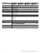
BIT WORD 88 0 Ultra DMA mode 0 is supported. 1 Ultra DMA mode 1 is supported. 2 Ultra DMA mode 2 is supported. 3 Ultra DMA mode 3 is supported. 4 Ultra DMA mode 4 is supported. 5 Ultra DMA mode 5 is supported. 6 Ultra DMA mode 6 is supported. 8 Ultra DMA mode 0 is currently active. 9 Ultra DMA mode 1 is currently active. 10 Ultra DMA mode 2 is currently active. 11 Ultra DMA mode 3 is currently active. 12 Ultra DMA mode 4 is currently active.
6.3.2 Set Features command This command controls the implementation of various features that the drive supports. When the drive receives this command, it sets BSY, checks the contents of the Features register, clears BSY and generates an interrupt. If the value in the register does not represent a feature that the drive supports, the command is aborted. Power-on default has the read look-ahead and write caching features enabled.
6.3.3 S.M.A.R.T. commands S.M.A.R.T. provides near-term failure prediction for disk drives. When S.M.A.R.T. is enabled, the drive monitors predetermined drive attributes that are susceptible to degradation over time. If self-monitoring determines that a failure is likely, S.M.A.R.T. makes a status report available to the host. Not all failures are predictable. S.M.A.R.T. predictability is limited to the attributes the drive can monitor. For more information on S.M.A.R.T.
42 CONSTELLATION ES.3 SERIAL ATA PRODUCT MANUAL, REV.
INDEX A ACA 23 acoustics 21 Active 17 Active mode 17 actuator arm 8 Admin SP 30 AES-256 data encryption 30 Agency certification 23 altitude 20 ambient 20 ambient temperature 8 Annualized Failure Rate (AFR) 22 areal density 3, 7 ATA commands 34 Australia/New Zealand Standard AS/NZ CISPR22 23 Australian Communication Authority (ACA) 23 Australian C-Tick 23 average idle current 9, 10, 11, 12 B Band 0 31 BandMasterX 30 BPI 7 C cables and connectors 26 capacity 7 CBC 30 CE mark 23 certification 23 Check Power
I P I/O data-transfer rate 7 Identify Device 34 Identify Device command 36 Idle 17, 34 Idle Immediate 34 Idle mode 8, 17 Information Technology Equipment (ITE) 23 Input noise ripple 17 input voltage 8 interface 7, 33 interference 23 internal data-transfer rate OD 7 ISO document 7779 21 ITE 23 password 30 passwords 30 PDT 22 peak operating current 9, 10, 11, 12 Physical characteristics 7 point-to-point 4, 26 Power consumption 8 power consumption 8 Power modes 17 Power specifications 8 PowerCycle 31 Power-
INDEX relative humidity 20 Reliability 22 Request Sense Data Ext 34 RF 22 RMS read/write current 17 RNG 30 RoHS 24 RRL 23 S S.M.A.R.T. Disable Operations 35 S.M.A.R.T. Enable Operations 35 S.M.A.R.T. Enable/Disable Autosave 35 S.M.A.R.T. Execute Offline 35 S.M.A.R.T. implementation 34 S.M.A.R.T. Read Attribute Thresholds 35 S.M.A.R.T. Read Data 35 S.M.A.R.T. Read Log Sector 35 S.M.A.R.T. Return Status 35 S.M.A.R.T. Save Attribute Values 35 S.M.A.R.T.
46 CONSTELLATION ES.3 SERIAL ATA PRODUCT MANUAL, REV.
Seagate Technology LLC AMERICAS Seagate Technology LLC 10200 South De Anza Boulevard, Cupertino, California 95014, United States, 408-658-1000 ASIA/PACIFIC Seagate Singapore International Headquarters Pte. Ltd. 7000 Ang Mo Kio Avenue 5, Singapore 569877, 65-6485-3888 EUROPE, MIDDLE EAST AND AFRICA Seagate Technology SAS 16-18 rue du Dôme, 92100 Boulogne-Billancourt, France, 33 1-4186 10 00 Publication Number: 100671511, Rev.