HP ProLiant DL585 Server Maintenance and Service Guide Part number: 358708-009 Ninth edition: May 2006
Legal notices © Copyright 2004–2006 Hewlett-Packard Development Company, L.P. The information contained herein is subject to change without notice. The only warranties for HP products and services are set forth in the express warranty statements accompanying such products and services. Nothing herein should be construed as constituting an additional warranty. HP shall not be liable for technical or editorial errors or omissions contained herein. Microsoft, Windows, and Windows NT are U.S.
Contents 1 About this guide Audience assumptions .............................................................................................................................. 5 Technician notes ...................................................................................................................................... 5 Where to go for additional help ................................................................................................................ 5 Integrated Management Log .......
BBWC assembly .................................................................................................................................... 44 SCSI backplane ..................................................................................................................................... 45 System battery ....................................................................................................................................... 46 System board ...........................................
1 About this guide This maintenance and service guide can be used for reference when servicing the HP ProLiant DL585 Server. WARNING! To reduce the risk of personal injury from electric shock and hazardous energy levels, only authorized service technicians should attempt to repair this equipment. Improper repairs can create conditions that are hazardous. Audience assumptions This guide is for service technicians.
Integrated Management Log The server includes an integrated, nonvolatile management log that contains fault and management information. The contents of the Integrated Management Log (IML) can be viewed with HP SIM. Telephone numbers For the name of the nearest HP authorized reseller: • In the United States, see http://www.hp.com/service_locator. • In Canada, see http://www.hp.com. For HP technical support: • In the United States and Canada, call 1-800-HP-INVENT (1-800-474-6836).
2 Illustrated parts catalog Customer self-repair program The HP customer self-repair program offers you the fastest service under either warranty or contract. It enables HP to ship replacement parts directly to you so that you can replace them. Using this program, you can replace parts at your own convenience. Through this convenient, easy-to-use program: • An HP support specialist will diagnose and assess whether a replacement part is required to address a system problem.
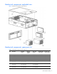
Mechanical components exploded view Figure 1 Mechanical components exploded view Mechanical components spare parts list Table 1 Mechanical components spare parts list Item Description Assembly number Modified assembly number Spare part number Modified spare part number Customer selfrepair (Yes/No) 1 Access panel 321466-001 — 359772-001 — Yes 2 Front bezel 233588-002 — 243669-001 — Yes 3 SCSI hard drive blank 302531-002 — 122759-001 — Yes 4 Hard drives — — — — — — 36-GB S
Table 1 Mechanical components spare parts list Modified assembly number Spare part number Modified spare part number Customer selfrepair (Yes/No) Item Description Assembly number — 146-GB SCSI hard drive, U320 10K* 271837-010‡ 404670-002 See requirement 289044-001‡ 404708-001 See requirement Yes — 146-GB SCSI hard drive U320 15K* 281837-028‡ 404670-006 See requirement 347779-001‡ 404712-001 See requirement Yes — 300-GB SCSI hard drive, U320 10K* 271837-021‡ 404670--001 See requirement 35
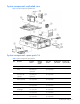
System components exploded view Figure 2 System components exploded view System components spare parts list Table 2 System components spare parts list Item Description Assembly number Modified assembly number Spare part number Modified spare part number Customer selfrepair (Yes/No) — Media storage devices — — — — — 1 CD-RW drive, universal media 2947669D1/9D2‡ See requirement 383696-002 337273-001‡ 399959-001 See requirement Yes 2a DVD-ROM drive, 8X, universal media (optional)* 168003
Table 2 System components spare parts list Modified assembly number Spare part number Modified spare part number Customer selfrepair (Yes/No) — — — — 011974-002‡ 011974-502 See requirement 356783-001 — Yes Processor memory board (PC2100/PC2700)** 011974-003‡ 011974-503 See requirement 382596-001‡ 412319-001 See requirement Yes — Processor memory board (PC3200)** 012567-001‡ 012567-501 See requirement 378476-001‡ 412321-001 See requirement Yes 9 Processors — — — — — — Processor,
Table 2 System components spare parts list Spare part number Modified spare part number Customer selfrepair (Yes/No) 012662-001‡ 012662-501 See requirement — — Yes — — 393535-001 — Yes SAS data cable assembly 361316-002 * — — — Yes — SAS power cable * 379196-001 — — — Yes 21 SAS array controller* 012335-001‡ 012335-501 See requirement 370855-001‡ 417343-001 See requirement Yes 22 SAS array cache (with battery)* 011773-002‡ 011773-502 See requirement 309522-001‡ 416828-001 See
Table 2 System components spare parts list Modified assembly number Spare part number Modified spare part number Customer selfrepair (Yes/No) Item Description Assembly number 37 1-GB, PC3200 (DDR SDRAM)* 373029-051‡ 373029-851 See requirement 378914-001‡ 416106-001 See requirement Yes 38 2-GB, PC3200 (DDR SDRAM)* 373030-051‡ 373030-851 See requirement 378915-001‡ 416107-001 See requirement Yes * Not shown **Mixing processor speeds or cache sizes is not supported ‡REQUIREMENT: For Customers
3 Removal and replacement procedures You need the following items for some procedures: • Torx T-15 tool • Flathead screwdriver • Diagnostics Utility on the HP SmartStart CD Safety considerations Before performing service procedures, review the following safety information. Electrostatic discharge A discharge of static electricity can damage static-sensitive devices or microcircuitry. Proper packaging and grounding techniques are necessary precautions to prevent damage.
IMPORTANT: If you are performing service procedures in an HP, Compaq branded, or third-party rack cabinet, you can use the locking feature of the rack rails to support the server and gain access to internal components. For more information about telco rack solutions, see the RackSolutions.com website at http://www.racksolutions.com/hp. • Access internal components. If you must access internal components for removal or replacement, you can remove the access panel without removing the server from the rack.
The system is now without power. Locating and removing the Torx T-15 tool Many hardware procedures in the server are toolless, but a few require the removal of Torx T-15 screws that have been installed for shipping or security reasons. A Torx T-15 tool ships with the server for the removal of these screws. 1. Locate the Torx T-15 tool on the back of the server. 2. Slide the tool upward out of the retaining clips. Figure 4 Removing the Torx T-15 tool Extending the server from the rack 1.
2. Extend the server on the rack rails until the server rail-release latches engage. Figure 6 Extending the server from the rack WARNING! Be careful when pressing the rail-release levers and sliding the component into or out of the rack. The sliding rails could pinch your fingertips. 3. After performing the installation or maintenance procedure, press the rail-release levers at the front of both server rails and slide the server into the rack. Figure 7 Sliding the server into the rack 4.
Removing the access panel WARNING! Pressing the Power On/Standby button sets the server to the standby position, which removes power from most areas of the server. However, portions of the power supply and some internal circuitry remain active until the AC power cord is removed. WARNING! To reduce the risk of personal injury from hot surfaces, allow the internal system components to cool before touching. CAUTION: Electrostatic discharge can damage electronic components.
Removing the server from the rack WARNING! The server is very heavy, up to 44.5 kg (98 lb). To reduce the risk of personal injury or damage to the equipment: • Remove all hot-plug power supplies to reduce the weight of the server before lifting it. • Observer local occupational health and safety requirements and guidelines for material handling. • Get help to lift and maneuver the server. To remove the server from the rack: 1. Power down the server.
Processor memory boards The server supports up to four processor memory boards with AMD® Opteron™ processors. CAUTION: Processor memory boards 1 and 2 must always be installed. The system will not boot if either board is missing. CAUTION: Update the ROM to be sure that the system ROM recognizes the new processor you are installing. For the most recent ROMPaq, see the HP website, and follow the support link on the product website.
4. Remove the processor memory board. Figure 11 Removing a processor memory board Reverse the steps to install a processor memory board. PPM To remove a Power Processor Module (PPM): 1. Power down the server. See “Powering down the server” earlier in this chapter. 2. Extend the server from the rack. See “Extending the server from the rack” earlier in this chapter. 3. Remove the access panel. See “Removing the access panel” earlier in this chapter. 4. Remove the processor memory board.
Processor Removing a processor 1. Power down the server. See “Powering down the server” earlier in this chapter. 2. Extend the server from the rack. See “Extending the server from the rack” earlier in this chapter. 3. Remove the access panel. See “Removing the access panel” earlier in this chapter. 4. Remove the processor memory board. See “Processor memory boards” earlier in this chapter. 5. Remove the processor heatsink. Figure 13 Removing the processor heatsink 6. Remove the processor.
3. Set the processor into the ZIF socket, and hold it in place while closing and latching the socket lever. Verify that the processor is fully seated in the socket. CAUTION: Failure to fully seat and latch the processor in the ZIF socket can result in damage to the processor, processor memory board, or both. 4.
Memory options Minimum memory requirements • Two DIMMs must be installed in bank 1 on the processor memory board in slot two. • All DIMMs on a processor memory board must have the same part number. NOTE: Processor memory boards in slots 1, 3, and 4 can be installed without memory. Certain application programs run more efficiently if the DIMMs are balanced across all processor memory boards.
Figure 16 Four DIMM slots Table 5 Processor memory board memory banks with four DIMM slots Slot Bank 5–6 Bank 1 7–8 Bank 2 Removing a DIMM 1. Power down the server. See “Powering down the server” earlier in this chapter. 2. Extend the server from the rack. See “Extending the server from the rack” earlier in this chapter. 3. Remove the access panel. See “Removing the access panel” earlier in this chapter. 4. Remove the processor memory board.
Hard drive blanks To remove a hard drive blank: 1. Push the sliding release button to unlock the blank . 2. Pull the drive blank out of the drive cage . Figure 18 Removing a drive blank NOTE: Keep the blank for future use. Reverse the steps to replace a drive blank. Hot-plug SCSI hard drives Drive replacement precautions Be aware of the following guidelines cautioning unsafe hot-plug replacement. • Do not remove a degraded drive if any other member of the array is offline (the online LED is off).
CAUTION: Remove or replace a hard drive only when the drive failure LED is amber. Data loss can occur if a drive is removed when the drive online LED is green. See “Hot-plug SCSI hard drive LEDs” in Chapter 4, “Server component identification,” for more information. CAUTION: Remove or replace only one hard drive at a time. The controller relies on other drives to reconstruct data on the replaced drive. Drive reconstruction is active when the drive online LED is flashing green.
• The system automatically sets all drive numbers. • If only one hard drive is used, install it in the bay with the lowest number. • Hard drives must be SFF types. • Drives must be the same capacity to provide the greatest storage space efficiency when drives are grouped together into the same drive array. CAUTION: Remove or replace a hard drive only when the drive failure LED is amber. Data loss can occur if a drive is removed when the drive Online/Activity status LED is green.
5. Remove the screws securing the hard drive cage. Figure 22 Removing the hard drive cage screws 6. Slowly pull the SAS hard drive cage out of the server until there is enough room to reach behind the SAS hard drive cage. 7. Disconnect all cables from the back of the SAS hard drive cage, and slide the hard drive cage out of the server. Reverse the steps to replace the SAS-SATA hard drive cage. Power transfer board 1. Power down the server. See “Powering down the server” earlier in this chapter. 2.
Figure 24 Removing the power transfer board Reverse the steps to replace the power transfer board.
Power supply blank To remove a power supply blank: 1. Press the lever-release button on the handle of the power supply blanks . 2. Pull on the lever to release the blank . 3. Remove the power supply blank from the server . Figure 25 Removing a power supply blank NOTE: Keep the power supply blank for future use. Reverse the steps to replace the power supply blank.
Hot-plug power supplies For information on power supply diagnosis, see “Hot-plug power supply LEDs” in Chapter 4, “Server component identification.” CAUTION: Do not remove a hot-plug power supply unless two power supplies are installed. If a second power supply is not installed, the system must be powered down to remove the power supply. CAUTION: Hot-plug power supplies for the server are keyed to be sure that only 800-W hot-plug power supplies can be installed in the server.
Hot-plug fans The server supports redundant hot-plug fans in a 7+1 configuration. To replace a hot-plug fan: 1. Extend the server from the rack. See “Extending the server from the rack” earlier in this chapter. 2. Remove the access panel. See “Removing the access panel” earlier in this chapter. 3. Identify the nonfunctioning fan by looking for an amber LED on the QuickFind diagnostic display or on the failed fan. 4. Remove the nonfunctioning fan. Figure 27 Removing a hot-plug fan 5.
Figure 28 Removing a drive from bay 1 Figure 29 Removing a drive from bay 2 To replace a universal media drive, slide the drive into the slot until it engages the connector. IMPORTANT: For the diskette drive to be bootable, it must be installed in the top universal media drive bay. For the CD-ROM or DVD-ROM drive to be bootable, it must be installed in the bottom universal media drive bay.
Front bezel To remove the front bezel: 1. Power down the server. See “Powering down the server” earlier in this chapter. 2. Extend the server from the rack. See “Extending the server from the rack” earlier in this chapter. 3. Remove the access panel. See “Removing the access panel” earlier in this chapter. 4. Using the T-15 Torx tool, remove the six screws on the exterior of the chassis and the two screws on the interior of the chassis next to the universal media drive bays.
Power button/LED assembly To remove the power button/LED assembly: 1. Power down the server. See “Powering down the server” earlier in this chapter. 2. Extend the server from the rack. See “Extending the server from the rack” earlier in this chapter. 3. Remove the access panel. See “Removing the access panel” earlier in this chapter. 4. Unplug the cable from the diagnostic display board. 5. Push the locking tab until the opposite side comes out.
Expansion boards The server supports the installation of PCI and PCI-X expansion boards.
Performance balancing Balancing is the paired arrangement of expansion boards for optimal performance based on the bus architecture of the expansion slots. Properly balancing the boards across buses can improve performance. To balance expansion boards: • Populate slots 1 and 2 with 133-MHz PCI-X boards. • Populate slots 3 through 8 with 100-MHz PCI-X boards. • Populate slots across different buses before populating two slots on the same bus.
SCSI cables To remove the SCSI cables: 1. Power down the server. See “Powering down the server” earlier in this chapter. 2. Extend the server from the rack. See “Extending the server from the rack” earlier in this chapter. 3. Remove the access panel. See “Removing the access panel” earlier in this chapter. 4. Disconnect the SCSI cables from the SCSI backplane. 5. Disconnect the SCSI cables from the PCI-X expansion boards.
Front fan cage To remove the front fan cage: 1. Power down the server. See “Powering down the server” earlier in this chapter. 2. Extend the server from the rack. See “Extending the server from the rack” earlier in this chapter. 3. Remove the access panel. See “Removing the access panel” earlier in this chapter. 4. Remove the processor memory boards. See “Processor memory boards” earlier in this chapter. 5. Remove the PCI-X expansion boards. See “PCI-X expansion boards” earlier in this chapter. 6.
Pass-through board To remove the pass-through board: 1. Power down the server. See “Powering down the server” earlier in this chapter. 2. Extend the server from the rack. See “Extending the server from the rack” earlier in this chapter. 3. Remove the access panel. See “Removing the access panel” earlier in this chapter. 4. Remove the processor memory boards. See “Processor memory boards” earlier in this chapter. 5. Remove the PCI-X expansion boards.
QuickFind diagnostic display board and lightpipe To remove the QuickFind diagnostic display board and lightpipe: 1. Power down the server. See “Powering down the server” earlier in this chapter. 2. Extend the server from the rack. See “Extending the server from the rack” earlier in this chapter. 3. Remove the access panel. See “Removing the access panel” earlier in this chapter. 4. Remove the processor memory boards. See “Processor memory boards” earlier in this chapter. 5.
Rear fan cage To remove the rear fan cage: 1. Power down the server. See “Powering down the server” earlier in this chapter. 2. Extend the server from the rack. See “Extending the server from the rack” earlier in this chapter. 3. Remove the access panel. See “Removing the access panel” earlier in this chapter. 4. Remove the processor memory boards. See “Processor memory boards” earlier in this chapter. NOTE: It is not necessary to remove the fans before removing the fan cage.
BBWC assembly IMPORTANT: The Battery-Backed Write Cache Enabler (BBWCE) and the 5i Plus BBWC Module must be removed together with the cable connected to save the data in the cache. Unplugging the cable deletes all the data in the cache. To remove the BBWC assembly: 1. Power down the server. See “Powering down the server” earlier in this chapter. 2. Extend the server from the rack. See “Extending the server from the rack” earlier in this chapter. 3. Remove the access panel.
SCSI backplane To remove the SCSI backplane: 1. Extend the server from the rack. See “Extending the server from the rack” earlier in this chapter. 2. Power down the server. See “Powering down the server” earlier in this chapter. 3. Unseat all the hot-plug SCSI hard drives, and pull them away from the SCSI backplane. See “Hot-plug SCSI hard drives” earlier in this chapter. NOTE: If you plan to take the hard drives out of the drive cage, label them so that they will be installed in the same slot. 4.
System battery WARNING! This server contains an internal lithium manganese dioxide or vanadium pentoxide battery. A risk of fire and burns exists if the battery is not handled properly. To reduce the risk of personal injury: • Do not attempt to recharge the battery. • Do not expose to temperatures higher than 60°C (140°F) CAUTION: Do not dispose of batteries, battery packs, and accumulators with the general household waste.
5. Remove the existing battery. Figure 43 Removing the battery from the system board 6. Install the new battery. 7. Install the access panel. 8. Restore the server to its operating position in the rack. 9. Run RBSU to reconfigure the system if the settings were lost.
System board To remove the system board: 1. Power down the server. See “Powering down the server” earlier in this chapter. 2. Remove all power supplies. See “Hot-plug power supply” earlier in this chapter. NOTE: Label the individual hard drives before pulling them out. 3. Remove all the hot-plug SCSI hard drives. See “Hot-plug SCSI hard drives” earlier in this chapter. 4. Extend the server from the rack. See “Extending the server from the rack” earlier in this chapter.
14. Remove the lower foam air baffle. 15. Unscrew the system board thumbscrews. It might be necessary to use the Torx tool located on the back of the server. 16. Slide the system board toward the front of the unit. Figure 44 Unscrewing the thumbscrews and sliding the system board IMPORTANT: When handling the system board, place your hands on the two handles only. 17. Grasping the two handles, lift the side with the processor memory board slots first, tilting the board to a 45° angle . 18.
AC filter cable assembly The AC filter cable assembly consists of two cables leading from separate power supply input connectors near the front of the chassis and ending in an AC filter and inlets at the rear of the chassis. To remove the AC filter cable: 1. Power down the server. See “Powering down the server” earlier in this chapter. 2. Remove all power supplies. See “Hot-plug power supply” earlier in this chapter. NOTE: Label the individual hard drives before pulling them out. 3.
16. Remove the seven cable clips: a. Lift to disengage the cable clip. b. Slide the clip forward, and lift it off the chassis. Figure 47 Removing the cable clips 17. Use the Torx T-15 tool or screwdriver to remove the eight screws that secure the power supply connectors to the chassis bottom . 18. Remove the cords from the connectors . 19. Remove the connectors from the server . Figure 48 Removing the power supply connectors 20.
21. Slide the assembly into the chassis, and then lift the assembly out of the chassis . Figure 49 Removing the AC filters Reverse the steps to replace the AC filter cable assembly.
Re-entering the server serial number After replacing the system board or clearing the NVRAM, re-enter the server serial number. 1. To access RBSU, press the F9 key when prompted during POST. 2. Select the System Options menu. 3. Select Serial Number. The following warning appears: WARNING! WARNING! WARNING! The serial number is loaded into the system during the manufacturing process and should NOT be modified. This option should ONLY be used by qualified service personnel.
4 Diagnostic tools Table 7 Diagnostic tools Tool Description How to run the tool Array Diagnostics Utility (ADU) ADU is designed to run on all ProLiant systems that support HP array controllers. ADU collects information about the array controllers in the system and generates a list of detected problems. For a list of HP servers that support ADU, follow the support link on product website at http://www.hp.com. For a complete list of ADU error messages, see the HP Servers Troubleshooting Guide.
Table 7 Diagnostic tools Tool Description How to run the tool ROM-Based Setup Utility (RBSU) RBSU configures the hardware installed Run RBSU by pressing the F9 key during in or connected to the server. POST.
5 Server component identification This chapter explains the location and function of system connectors, internal and external LEDs, and system switches. Connectors Use this section to identify system connectors for service procedures.
SCSI backplane Figure 51 SCSI backplane board connectors Table 9 SCSI backplane board connectors Item Description 1 SCSI channel A 2 SCSI simplex/duplex switch (default = duplex) 3 SCSI channel B Server component identification 57
DIMM slots Figure 52 DIMM slots Table 10 Processor memory board memory banks Slot Bank 1–2 Bank 1 3–4 Bank 2 5–6 Bank 3 7–8 Bank 4 Processor and PPM Figure 53 Processor and PPM Table 11 Processor and PPM Item Description 1 PPM 2 Processor and heatsink Server component identification 58
LEDs The server contains several sets of LEDs that indicate the status and settings of hardware components.
QuickFind diagnostic display Figure 55 QuickFind diagnostic display LEDs Table 13 Quickfind diagnostic display LEDs Item Description Status Action 1 Fan Off = Normal On = Attention required Be sure the fan is installed and seated properly. If the fan is installed and seated properly, replace the fan. 2 Processor Off = Normal On = Attention required Processor pre-failure notification. Inspect the IML logs, POST messages, or both. The processor might need to be replaced.
Table 13 Quickfind diagnostic display LEDs Item Description Status Action 7 I/O power fault Off = Normal On = Attention required A power fault on the system I/O board occurred. If the problem persists, replace the system I/O board. 8 Therm trip Off = Normal On = Attention required The server experienced a thermal shutdown. If one of the CPU thermal LEDs is amber, that CPU experienced an overtemperature condition. Be sure that the processor heatsink is properly attached.
Table 14 Hot-plug SCSI hard drive LEDs Item Description Status 3 Fault status On = Drive failure Flashing = Fault-process activity Off = No fault-process activity Table 15 Hot-plug SCSI hard drive LED combinations Activity LED Online LED Fault LED Status On Off Off Do not remove the drive. Removing a drive during this process will cause data loss. The drive is being accessed and is not configured as part of an array. On Flashing Off Do not remove the drive.
Hot-plug SAS or SATA hard drives Figure 57 Hot-plug SAS or SATA hard drive LEDs Table 16 Hot-plug SAS or SATA hard drive LEDs Item Description Status 1 Fault/UID status Amber = Drive failure Flashing Amber = Fault-process activity Blue = Unit identification is active Off = No fault-process activity 2 Online/Activity Status Green = Drive activity Flashing green = High activity on the drive or the drive is being configured as part of an array Off = No drive activity Table 17 Hot-plug SAS or SATA har
Table 17 Hot-plug SAS or SATA hard drive LED combinations Online/Activity LED (green) Fault/UID LED (amber/blue) Interpretation Flashing regularly (1 Hz) Off Do not remove the drive. Removing a drive may terminate the current operation and cause data loss. The drive is rebuilding, or it is part of an array that is undergoing capacity expansion or stripe migration.
Hot-plug fans Figure 58 Hot-plug fan LED The hot-plug fan LED indicates the following conditions: Table 18 Hot-plug fan LED LED status Description Off Power is not applied to the fan Green Power is applied to the fan Amber Fan failure Hot-plug power supplies Figure 59 Hot-plug power supply LEDs Table 19 Hot-plug power supply LEDs (1) Power LED status (green) (2) Fault LED status (amber) Description Off Off No AC power Off On No AC power to power supply -OrPower supply failure Server compo
Table 19 Hot-plug power supply LEDs (1) Power LED status (green) (2) Fault LED status (amber) Description Blinking Off AC power present System in standby mode On Off Power supply on and working properly On Blinking Power supply current limit exceeded NIC Figure 60 NIC LEDs Table 20 NIC LEDs Item Description LED color Status 1 Activity LED Green On or flashing = Network activity Off = No network activity 2 Link LED Green On = Linked to the network Off = Not linked to the network Serv
BBWCE Figure 61 BBWCE LEDs NOTE: The battery takes 24 hours to charge for the first time. Table 21 BBWCE LEDs Server status LED color LED status Battery module status Server is on and has normal run time.
Internal diagnostic display Figure 62 Internal diagnostic display LEDs and switches Table 22 Internal diagnostic display switches Item Switch 1 Switch 2 Description Port 84 Off Off For more information on Port 84, see the Port 84 diagnostic codes that occur during the boot process. Reserved Off On N/A iLO On Off For more information on iLO, see the Integrated Lights-Out User Guide.
System board switches Some server operations, including adding or removing a component or changing a security feature, require that you reconfigure a system switch. If the system configuration is incorrect, the server might not work properly and you might receive error messages on the screen. Setting and checking the system board switches is an important part of the overall troubleshooting process.
Table 23 System maintenance switch (SW3) Position Default Function Description Settings 5 Off Password disable Enables or disables password protection. Open (off) Power-on password is enabled. Closed (on) Power-on password is disabled. 6 Off Configuration validation Invalidates NVRAM configuration information. Open (off) NVRAM is valid. Closed (on) NVRAM is invalid, and configuration is lost.
iLO/Redundant ROM override switch (SW5) The iLO/Redundant ROM override switch (SW5) is a two-position switch that is used for miscellaneous purposes. The iLO security override switch allows you full access to the iLO processor. This access is necessary if you lost your password or if the iLO boot-block must be flashed.
Non-maskable interrupt switch Crash dump analysis is an essential part of eliminating reliability problems such as hangs or crashes in operating systems, device drivers, and applications. Crashes can freeze a system, requiring you to do a hard reset. Resetting the system erases any information that supports root cause analysis. Systems running supported Microsoft operating systems experience a blue screen trap when the operating system crashes.
6 Troubleshooting This chapter provides specific troubleshooting information for the server. Use it to find details about server startup and operation errors. For information on LEDs and switches specific to the server, see Chapter 4, “Server component identification.” For a more detailed discussion of troubleshooting techniques, diagnostic tools, error messages, and preventative maintenance, see the HP Servers Troubleshooting Guide included on the Documentation CD that ships with the server.
If the server does not start This section provides systematic instructions on what to try and where to go for help for the most common problems encountered during initial POST. The server must first complete this test each time you power up, before it can load the operating system and start running software applications. WARNING! A risk of personal injury exists from hazardous energy levels.
Diagnostic steps If the server does not power up or powers up but does not complete POST, answer the questions in Table 27 to determine appropriate actions based on the symptoms observed. The flow of questions reflects the usual flow of events during a power-on sequence. A flow chart following this table illustrates the recommended diagnostic steps and decision options. According to the answers you give, you will be directed to an appropriate secondary table in this section.
Table 29 Is the system power LED green? Answer Possible reasons Possible solutions — A power supply problem exists. The power supply may not be connected or inserted properly, it may have a damaged connector, or it may have failed. Be sure that the power supply is undamaged, the power supply is fully seated, and the power supply LED is green. — The system may have experienced a short. Check for bent connector pins and improperly seated expansion boards. — The front panel LED assembly has failed.
Table 31 Is the internal health LED green? Answer Possible reasons Possible solutions No, it is amber A processor is in pre-failure condition. A DIMM is in pre-failure condition. One memory bank is valid, but another bank is missing a DIMM. One memory bank is valid, but another bank has mismatched DIMMs installed. One memory bank is valid, but another bank has an unsupported DIMM type installed. A redundant fan has failed.
Table 31 Is the internal health LED green? Answer Possible reasons Possible solutions — PPM or board power fault Inspect the QuickFind diagnostic display panel to determine if one of the PPMs, processor memory boards, or system board has experienced a power fault. Ensure that all components are seated properly. If problem persists, replace the failed component. A PPM failure will be shown by the PPM LED being illuminated on the specific processor memory board.
Table 32 Is the monitor displaying information? Answer Yes Possible reasons Possible solutions Video is available for diagnosis. Determine the next action by observing POST progress and error messages. See the HP Servers Troubleshooting Guide for a complete description of each POST error message.
Problems after initial boot After the server has passed POST, you might still encounter errors, such as an inability to load the operating system. Use Table 33 to troubleshoot server installation problems that occur after the initial boot. See the HP Servers Troubleshooting Guide for more information. Table 33 Problems after initial boot Problem Possible reasons Possible solutions System cannot load ProLiant Essentials Foundation Pack. ProLiant Essentials Foundation Pack requirements not met.
Table 33 Problems after initial boot Problem Possible reasons Possible solutions — Problem was encountered with hardware You must complete the factory-installed added to a new configure-to-order operating system software installation system (where available). before adding new hardware to the system. Be sure you are following the instructions provided in the Factory-Installed Operating System Software Installation Guide. Remove the new hardware and complete the software installation.
Troubleshooting a failed processor The AMD HyperTransport™ link architecture links multiple processors. When a processor failure occurs, the root cause of the problem can be either a failed HyperTransport link or a failed processor. A failed processor or failed HyperTransport link causes the system to hang at POST without video. Perform the steps outlined in the following sections to isolate a failed component in a two- or four-processor memory board configuration.
Other information resources See the following additional information for help. Table 34 Troubleshooting resources Resource Description HP Servers Troubleshooting Guide This guide is a resource for obtaining troubleshooting information that is beyond the scope of this document. It includes general hardware and software troubleshooting information for all ProLiant servers, a complete list of error messages along with explanations of probable causes, and a list of remedial measures.
Specifications Server specifications Table 35 Server specifications Feature Units Dimensions Height 17.5 cm (6.88 in) Depth 69.2 cm (27.25 in) Width 46.3 cm (19.0 in) Weight 30.8 kg, minimum (68 lb, minimum) 44.
Index A E AC filter cable, 50 AC power supply. See hot-plug power supply access panel: installing, 18; removing, 18 additional information, 5 ADU. See Array Diagnostics Utility Array Diagnostics Utility (ADU), 54 ASR-2. See Automatic Server Recovery-2 Automatic Server Recovery-2 (ASR-2), 54 electrostatic discharge (ESD), 14 electrostatic-sensitive parts, precautions, 14 error messages, POST, 79 ESD.
P pass-through board, 41 PCI-X buses, numbering, 38 PCI-X non-hot-plug expansion board: removing, 38; replacing, 38 PCI-X technology: features, 37; load balancing, 37; peak frequency, 37; performance balancing, 38; slot population, 38 port 84 switch, 68 POST error messages, 79 power button/LED assembly, 36 power LED, 59 Power Processor Module. See PPM power supply.