SATA Product Manual Standard 512E model ST14000NE0008 ST12000NE0008 ST10000NE0008 100835984, Rev.
Document Revision History Revision Date Rev. A 05/17/2018 Initial release. Rev.
Contents Seagate® Technology Support Services . . . . . . . . . . . . . . . . . . . . . . . . . . . . . . . . . . . . . . . . . . . . . . . . . . . . . . . . . . . . . . . 4 1.0 Introduction . . . . . . . . . . . . . . . . . . . . . . . . . . . . . . . . . . . . . . . . . . . . . . . . . . . . . . . . . . . . . . . . . . . . . . . . . . . . . . . . . 5 1.1 About the Serial ATA interface . . . . . . . . . . . . . . . . . . . . . . . . . . . . . . . . . . . . . . . . . . . . . . . . . . . . . . . . . . . .
Contents 3.0 Configuring and mounting the drive . . . . . . . . . . . . . . . . . . . . . . . . . . . . . . . . . . . . . . . . . . . . . . . . . . . . . . . . . 20 3.1 Handling and static-discharge precautions . . . . . . . . . . . . . . . . . . . . . . . . . . . . . . . . . . . . . . . . . . . . . . . . . . . 20 3.2 Configuring the drive . . . . . . . . . . . . . . . . . . . . . . . . . . . . . . . . . . . . . . . . . . . . . . . . . . . . . . . . . . . . . . . . . . . . . . . . 20 3.
Seagate® Technology Support Services For Seagate Product Support, visit: https://www.seagate.com/support For Seagate Compliance, Safety, and Disposal, visit: https://www.seagate.com/support For Firmware Download and Tools Download for Secure Erase, visit: https://www.seagate.com/support/downloads/ For information regarding online support and services, visit: http://www.seagate.com/contacts/ For information regarding Warranty Support, visit: http://www.seagate.
www.seagate.com 1.1 Introduction Introduction This manual describes the functional, mechanical and interface specifications for the following: Seagate® IronWolf® Pro Serial ATA drive models. Table 1: Models Standard 512E models ST14000NE0008 ST12000NE0008 ST10000NE0008 These drives provide the following key features: 256 MB data buffer. 7200 RPM spindle speed. Full-track multiple-sector transfer capability without local processor intervention.
www.seagate.com 1.1.1 Introduction About the Serial ATA interface The Serial ATA interface provides several advantages over the traditional (parallel) ATA interface. The primary advantages include: Easy installation and configuration with true plug-and-play connectivity. It is not necessary to set any jumpers or other configuration options. Thinner and more flexible cabling for improved enclosure airflow and ease of installation. Scalability to higher performance levels.
www.seagate.com 1.2 Drive specifications Drive specifications Unless otherwise noted, all specifications are measured under ambient conditions, at 25°C, and nominal power. For convenience, the phrases the drive and this drive are used throughout this manual to indicate the IronWolf Pro Serial ATA drive models. 1.2.1 Specification summary tables The specifications listed in the following tables are for quick reference.
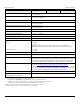
www.seagate.com Drive specifications Drive specification# ST14000NE0008 Temperature gradient (°C per hour max) 20°C (operating) 20°C (nonoperating) Relative humidity* 5% to 95% (operating) 5% to 95% (nonoperating) Relative humidity gradient 20% per hour max Altitude, operating –304.8 m to 3,048 m (–1000 ft to 10,000+ ft) ST12000NE0008 ST10000NE0008 Altitude, nonoperating (below mean sea level, max) –304.
www.seagate.com 1.2.2 Drive specifications Formatted capacity ST models Formatted capacity* Guaranteed sectors ST14000NE0008 14TB 27,344,764,928 ST12000NE0008 12TB 23,437,770,752 ST10000NE0008 10TB 19,532,873,728 Bytes per logical sector 512E *One GB equals one billion bytes when referring to hard drive capacity. Accessible capacity may vary depending on operating environment and formatting. NOTE 1.2.2.
www.seagate.com 1.2.5 Drive specifications Power specifications The drive receives DC power (+5V or +12V) through a native SATA power connector. See Figure 2 on page 20 . 1.2.5.1 Power consumption Power requirements for the drives are listed in Table 3. Typical power measurements are based on an average of drives tested, under nominal conditions, using 5.0V and 12.0V input voltage at 25°C ambient temperature. Table 3 DC power requirements 6.
www.seagate.com 1.2.5.1.1 Figure 1. Drive specifications Typical current profiles Typical 5V and 12V startup and operation current profiles Seagate IronWolf Pro Serial ATA Product Manual, Rev.
www.seagate.com 1.2.5.2 Drive specifications Conducted noise Noise is specified as a periodic and random distribution of frequencies covering a band from DC to 10 MHz. Maximum allowed noise values given below are peak-to-peak measurements and apply at the drive power connector. +5v = 250 mV pp from 100 Hz to 20 MHz. +12v = 800 mV pp from 100 Hz to 8 KHz. 450 mV pp from 8 KHz to 20 KHz. 250 mV pp from 20 KHz to 5 MHz. 1.2.5.3 Voltage tolerance Voltage tolerance (including noise): 5V ± 5% 1.2.5.
www.seagate.
www.seagate.com Drive specifications PowerChoice Supported Extended Power Condition Identifiers Power Condition Identifiers Power Condition Name 00H Standby_z 01 - 80H Reserved 81H Idle_a 82H Idle_b 83H Idle_c 84 - FEH Reserved FFH All EPC Power Conditions 2.6 Environmental limits Temperature and humidity values experienced by the drive must be such that condensation does not occur on any drive part. Altitude and atmospheric pressure specifications are referenced to a standard day at 58.
www.seagate.com 2.6.3 Drive specifications Shock and Vibration Shock and vibration measurements specified in this document are made directly on the drive itself and applied in the X, Y, and Z axis at the drive mounting point locations. 2.6.3.1 Shock a. Operating The drive will operate without error while subjected to intermittent shock pulses not exceeding 70 Gs (read) and 40 Gs (write) at a maximum duration of 2ms. b.
www.seagate.com 1.2.6 Drive specifications Acoustics Drive acoustics are measured as overall A-weighted acoustic sound power levels (no pure tones). All measurements are consistent with ISO document 7779. Sound power measurements are taken under essentially free-field conditions over a reflecting plane. For all tests, the drive is oriented with the cover facing upward. NOTE For seek mode tests, the drive is placed in seek mode only.
www.seagate.com Drive specifications 1.2.9 Reliability 1.2.9.1 Annualized Failure Rate (AFR) and Mean Time Between Failures (MTBF) The production disk drive shall achieve an annualized failure-rate of 0.73% (MTBF of 1,200,000 hours) over a 5 year service life when used in Enterprise Storage field conditions as limited by the following: 8760 power-on hours per year.
www.seagate.com 1.2.10 Drive specifications HDD and SSD Regulatory Compliance and Safety For the latest regulatory and compliance information see: https://www.seagate.com/support/ scroll to bottom of page and click the Seagate HDD and SSD Regulatory Compliance and Safety link. 1.2.10.1 Regulatory Models The following regulatory model number represent all features and configurations within the series: Regulatory Model Numbers: STL006 1.2.
www.seagate.com 1.2.
www.seagate.com 1.3 Configuring and mounting the drive Configuring and mounting the drive This section contains the specifications and instructions for configuring and mounting the drive. 1.3.1 Handling and static-discharge precautions After unpacking, and before installation, the drive may be exposed to potential handling and electrostatic discharge (ESD) hazards. Observe the following standard handling and static-discharge precautions: Caution 1.3.
www.seagate.com 1.3.4 Configuring and mounting the drive Drive mounting Users can mount the drive in any orientation using four screws in the side-mounting holes or four screws in the bottom-mounting holes. See Figure 3 for drive mounting dimensions. Follow these important mounting precautions when mounting the drive: 1.3.4.1 Allow a minimum clearance of 0.030 in (0.76mm) around the entire perimeter of the drive for cooling. Use only 6-32 UNC mounting screws.
www.seagate.com 1.4 Serial ATA (SATA) interface Serial ATA (SATA) interface These drives use the industry-standard Serial ATA interface that supports FIS data transfers. It supports ATA programmed input/output (PIO) modes 0–4; multiword DMA modes 0–2, and Ultra DMA modes 0–6. For detailed information about the Serial ATA interface, refer to the “Serial ATA: High Speed Serialized AT Attachment” specification. 1.4.
www.seagate.com Serial ATA (SATA) interface Notes: 1. All pins are in a single row, with a 1.27mm (0.050”) pitch. 2. The comments on the mating sequence apply to the case of backplane blindmate connector only. In this case, the mating sequences are: • the ground pins P4 and P12. • the pre-charge power pins and the other ground pins. • the signal pins and the rest of the power pins. 1.4.3 3. There are three power pins for each voltage.
www.seagate.
www.seagate.
www.seagate.com 1.4.3.1 Serial ATA (SATA) interface Identify Device command The Identify Device command (command code ECH) transfers information about the drive to the host following power up. The data is organized as a single 512-byte block of data, whose contents are shown in Table 7 on page 23. All reserved bits or words should be set to zero. Parameters listed with an “x” are drive-specific or vary with the state of the drive. see Section 1.2 on page 7for default parameter settings.
www.seagate.com Table 8 Serial ATA (SATA) interface Identify Device command Word Description Value 60–61 Total number of user-addressable LBA sectors available (see Section 1.2.2 for related information) *Note: The maximum value allowed in this field is: 0FFFFFFFh (268,435,455 sectors, 137GB). Drives with capacities over 137GB will have 0FFFFFFFh in this field and the actual number of user-addressable LBAs specified in words 100-103.
www.seagate.com Serial ATA (SATA) interface Table 8 Identify Device command Word Description Value 106 Physical/Logical sector size 6003H (512E) / 5000H (4KN) 107 ATA-reserved 0000H 108–111 The mandatory value of the world wide name (WWN) for the drive. NOTE: This field is valid if word 84, bit 8 is set to 1 indicating 64-bit WWN support. Each drive will have a unique value.
www.seagate.com Serial ATA (SATA) interface Description (if bit is set to 1) Bit Word 63 0 Multiword DMA mode 0 is supported. 1 Multiword DMA mode 1 is supported. 2 Multiword DMA mode 2 is supported. 8 Multiword DMA mode 0 is currently active. 9 Multiword DMA mode 1 is currently active. 10 Multiword DMA mode 2 is currently active. Bit Word 84 0 SMART error logging is supported. 1 SMART self-test is supported. 2 Media serial number is not supported.
www.seagate.com 1.4.3.2 Serial ATA (SATA) interface Identify Device Data log The IDENTIFY DEVICE Data log (log 30H) transfers information about the drive. The data is organized as a set of 512byte blocks of data, whose contents are shown in Table 2 on page 7. All reserved bits or words should be set to zero. Parameters listed with an "x" are drive-specific or vary with the state of the drive. The following may contain drive-specific features that may are included in the Serial ATA specification.
www.seagate.com Table 9 Serial ATA (SATA) interface Identify Device Data log (Continued) Capacity Capacity page information header (QWord) 0..7 63 Shall be set to 1 1 62:24 Reserved 23:16 Page number 02 15:0 Revision number 0001 Device Capacity (QWord) 8..15 63 Shall be set to 1 1 62:48 Reserved 0 47:0 accessible capacity 65DE00000 - (512E) CBBC0000 - (4KN) Physical/Logical Sector Size (QWord) 02 16..
www.seagate.
www.seagate.
www.seagate.com Table 9 Serial ATA (SATA) interface Identify Device Data log (Continued) Write-Read-Verify Sector Count Mode 2 (QWord) 63 Contents of the QWord are valid 1 62:32 Reserved 0 31:0 wrm mode 2 count 0 48..55 World wide name (DQWord) 127 Shall be set to one 1 126:64 Reserved 0 63:0 world wide name unique 56..71 DATA SET MANAGEMENT (QWord) 72..
www.seagate.com Table 9 Serial ATA (SATA) interface Identify Device Data log (Continued) Zoned Capabilities (QWord) 63 Contents of the QWord are valid 0 62:2 Reserved 0 1:0 zoned 0 104..111 Supported ZAC Capabilities (QWord) 63 Contents of the QWord are valid 0 62:5 Reserved 0 4 non-data reset write pointers ext supported 0 3 non-data finish zone ext supported 0 2 non-data close zone ext supported 0 1 non-data open zone ext supported 0 0 report zones ext supported 0 112..
www.seagate.com Table 9 Serial ATA (SATA) interface Identify Device Data log (Continued) Supported SCT Capabilities (QWord) 144..
www.seagate.
www.seagate.com Table 9 Serial ATA (SATA) interface Identify Device Data log (Continued) Streaming Minimum Request Size (QWord) 63 Contents of the QWord are valid 1 62:16 Reserved 0 15:0 stream min request size 1000H 40..47 Streaming Access Latency (QWord) 63 Contents of the QWord are valid 1 62:16 Reserved 0 15:0 stream access latency 0 48..55 Streaming Performance Granularity (QWord) 63 Contents of the QWord are valid 1 62:16 Reserved 0 15:0 stream granularity 2710H 56..
www.seagate.com Table 9 Serial ATA (SATA) interface Identify Device Data log (Continued) Strings Supported Capabilities page information header (QWord) 63 Shall be set to 1 62:24 Reserved 23:16 Page number 1 0..7 05 06 8..27 SERIAL NUMBER (ATA String) 28..31 Reserved 32..39 FIRMWARE REVISION (ATA String) 40..47 Reserved 48..87 MODEL NUMBER (ATA String) 88..95 Reserved 96..103 ADDITIONAL PRODUCT IDENTIFIER (ATA String) 104..
www.seagate.com Table 9 Serial ATA (SATA) interface Identify Device Data log (Continued) Time required for an Enhanced Erase mode SECURITY ERASE UNIT command (QWord) 24..31 63 Contents of the QWord are valid 1 62:16 Reserved 0 15 enhanced security erase time format 1 14:0 enhanced security erase time 245H Time required for an Normal Erase mode SECURITY ERASE UNIT command (QWord) 32..
www.seagate.com Table 9 Serial ATA (SATA) interface Identify Device Data log (Continued) Serial ATA page information header (QWord) 63 Shall be set to 1 62:24 Reserved 23:16 Page number 1 0..
www.seagate.com Table 9 Serial ATA (SATA) interface Identify Device Data log (Continued) Current SATA Settings (QWord) 16..
www.seagate.com 1.4.3.3 Serial ATA (SATA) interface Device Statistics log The Device Statistics log (log 04H) transfers information about the drive. The data is organized as a set of 512-byte blocks of data, whose contents are shown in Table 2 on page 7. All reserved bits or words should be set to zero. Parameters listed with an "x" are drive-specific or vary with the state of the drive. The following may contain drive-specific features that are included in the SATA specifications.
www.seagate.
www.seagate.com 1.4.3.4 Serial ATA (SATA) interface Set Features command This command controls the implementation of various features that the drive supports. When the drive receives this command, it sets BSY, checks the contents of the Features register, clears BSY and generates an interrupt. If the value in the register does not represent a feature that the drive supports, the command is aborted. Power-on default has the read look-ahead and write caching features enabled.
www.seagate.com 1.4.3.5 Serial ATA (SATA) interface S.M.A.R.T. commands S.M.A.R.T. provides near-term failure prediction for disk drives. When S.M.A.R.T. is enabled, the drive monitors predetermined drive attributes that are susceptible to degradation over time. If self-monitoring determines that a failure is likely, S.M.A.R.T. makes a status report available to the host. Not all failures are predictable. S.M.A.R.T. predictability is limited to the attributes the drive can monitor.
Seagate Technology LLC AMERICAS Seagate Technology LLC 47488 Kato Road, Fremont, California 94538, United States, 510-661-1000 Publication Number: 100835984, Rev.