Product Manual Standard models Self-Encryption models ST3000DM008 ST2000DM006 ST1000DM010 ST500DM009 ST3000DM009 ST2000DM007 100804187, Rev.
Document Revision History Revision Date Description of Change Rev. A 07/08/2016 Initial release. Rev. B 11/29/2016 fc: Placed new BarraCuda logo 19: Added MSIP Korean text for Class B device warning Rev. C 02/22/2017 23: Revised base deck option statement 25: Add Figure 5 mechanical drawing & note Rev. D 06/21/2017 8 & 11: Revised Max height to 20.20 mm 23-25: Revised Mechanical Drawings (Figs 3-5) Z-heights to 20.20 mm © 2017 Seagate Technology LLC. All rights reserved.
Contents Seagate® Technology Support Services . . . . . . . . . . . . . . . . . . . . . . . . . . . . . . . . . . . . . . . . . . . . . . . . . . . . . . . . . . . . . . . 5 1.0 Introduction . . . . . . . . . . . . . . . . . . . . . . . . . . . . . . . . . . . . . . . . . . . . . . . . . . . . . . . . . . . . . . . . . . . . . . . . . . . . . . . . . 6 1.1 About the SATA interface . . . . . . . . . . . . . . . . . . . . . . . . . . . . . . . . . . . . . . . . . . . . . . . . . . . . . . . . . . . . . . .
Contents 3.0 Configuring and Mounting the Drive . . . . . . . . . . . . . . . . . . . . . . . . . . . . . . . . . . . . . . . . . . . . . . . . . . . . . . . . . 21 3.1 Handling and static-discharge precautions . . . . . . . . . . . . . . . . . . . . . . . . . . . . . . . . . . . . . . . . . . . . . . . . . . . 21 3.2 Configuring the drive . . . . . . . . . . . . . . . . . . . . . . . . . . . . . . . . . . . . . . . . . . . . . . . . . . . . . . . . . . . . . . . . . . . . . . . . 21 3.
Figures Figure 1 Figure 2 Figure 3 Figure 4 Figure 5 Attaching SATA cabling. . . . . . . . . . . . . . . . . . . . . . . . . . . . . . . . . . . . . . . . . . . . . . . . . . . . . . . . . . . . . . . . . . . . . . . . Mounting dimensions (2/3-disk: 2TB to 3TB models) . . . . . . . . . . . . . . . . . . . . . . . . . . . . . . . . . . . . . . . . . . . . Mounting dimensions (configuration 1) . . . . . . . . . . . . . . . . . . . . . . . . . . . . . . . . . . . . . . . . . . . . . . . . . . . . . . . .
Seagate® Technology Support Services For information regarding online support and services, visit: http://www.seagate.com/contacts/ For information regarding Warranty Support, visit: http://www.seagate.com/support/warranty-and-replacements/ For information regarding data recovery services, visit: http://www.seagate.com/services-software/data-recovery-services/ For Seagate OEM, Distribution partner and reseller portals, visit: http://www.seagate.com/partners/ Seagate BarraCuda Product Manual, Rev.
www.seagate.com 1.0 Introduction Introduction This manual describes the functional, mechanical and interface specifications for the following: Seagate® BarraCuda® model drives: Standard models Self-Encryption models ST3000DM008 ST1000DM010 ST3000DM009 ST2000DM006 ST500DM009 ST2000DM007 Note Previous generations of Seagate Self-Encrypting Drive models were called Full Disk Encryption (FDE) models before a differentiation between drive-based encryption and other forms of encryption was necessary.
www.seagate.com 1.1 Introduction About the SATA interface The Serial ATA (SATA) interface provides several advantages over the traditional (parallel) ATA interface. The primary advantages include: • Easy installation and configuration with true plug-and-play connectivity. It is not necessary to set any jumpers or other configuration options. • Thinner and more flexible cabling for improved enclosure airflow and ease of installation. • Scalability to higher performance levels.
www.seagate.com 2.0 Drive Specifications Drive Specifications Unless otherwise noted, all specifications are measured under ambient conditions, at 25°C, and nominal power. For convenience, the phrases the drive and this drive are used throughout this manual to indicate the following drive models Standard models Self-Encryption models ST3000DM008 ST1000DM010 ST3000DM009 ST2000DM006 ST500DM009 ST2000DM007 2.
www.seagate.
www.seagate.com 2.2 Drive Specifications Formatted capacity Model Formatted capacity* Guaranteed sectors ST3000DM008 & ST3000DM009 3000GB 5,860,533,168 ST2000DM006 & ST2000DM007 2000GB 3,907,029,168 ST1000DM010 1000GB 1,953,525,168 ST500DM009 500GB 976,773,168 Bytes per sector 4096 *One GB equals one billion bytes and 1TB equals one trillion bytes when referring to hard drive capacity. Accessible capacity may vary depending on operating environment and formatting. 2.2.
www.seagate.com 2.5 Drive Specifications Physical characteristics Maximum height 3TB and 2TB 1TB and 500GB 26.1mm / 1.028 in 20.20mm / 0.795 in Maximum width (all models) 101.6mm / 4.0 in (± 0.010 in) Maximum length (all models) 146.99mm / 5.787 in Typical weight 3TB 626g / 1.38 lb 2TB 626g / 1.38 lb - or 535g / 1.18 lb 1TB and 500GB 400g / 0.88lb Cache buffer 2.6 3TB, 2TB and 1TB 64MB 500GB 32MB Seek time Seek measurements are taken with nominal power at 25°C ambient temperature.
www.seagate.com 2.7 Drive Specifications Start/stop times 3-disk (3TB models) Power-on to ready (in seconds) 2-disk (2TB models) 15 (typical) 17 (max) Power-on to ready (typical) Standby to ready (in seconds) Ready to spindle stop (in seconds) 1-disk (1TB models) 1-disk (500GB models) 10 (typical) 12 (max) 8.5 (typical) 10 (max) 10 (typical) 12 (max) 8.
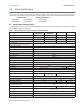
www.seagate.com Table 2 Drive Specifications DC power requirements (3-disk: 3TB and 2TB models) Power dissipation (3-disk values shown) Avg (watts 25° C) Avg 5V typ amps Avg 12V amps Spinup — — 2.0A or 2.5A Idle2* † 5.40 0.190 0.377 Operating 8.00 0.510 0.462 Standby 0.75 0.136 0.005 Sleep 0.75 0.136 0.005 Table 3 DC power requirements (1-disk: 1TB and 500GB models) Power dissipation (1-disk values shown) Avg (watts 25° C) Avg 5V typ amps Avg 12V typ amps Spinup — — 2.
www.seagate.com Drive Specifications 2.8.3 Voltage tolerance Voltage tolerance (including noise): • 5V ±5% • 12V +10% / -7.5% 2.8.4 Power-management modes The drive provides programmable power management to provide greater energy efficiency. In most systems, users can control power management through the system setup program.
www.seagate.com 2.9 Drive Specifications Environmental specifications This section provides the temperature, humidity, shock, and vibration specifications. Ambient temperature is defined as the temperature of the environment immediately surrounding the drive. Above 1000ft. (305 meters), the maximum temperature is derated linearly by 1°C every 1000 ft. Refer to Section 3.4 Drive mounting for base plate measurement location. 2.9.
www.seagate.com Drive Specifications 2.9.5 Shock All shock specifications assume that the drive is mounted securely with the input shock applied at the drive mounting screws. Shock may be applied in the X, Y or Z axis. 2.9.5.1 Operating shock These drives comply with the performance levels specified in this document when subjected to a maximum operating shock of 80 Gs based on half-sine shock pulses of 2 ms during read operations. Shocks should not be repeated more than two times per second. 2.9.5.
www.seagate.com Drive Specifications 2.10 Acoustics Drive acoustics are measured as overall A-weighted acoustic sound power levels (no pure tones). All measurements are consistent with ISO document 7779. Sound power measurements are taken under essentially free-field conditions over a reflecting plane. For all tests, the drive is oriented with the cover facing upward. Note For seek mode tests, the drive is placed in seek mode only.
www.seagate.com Drive Specifications 2.12 Reliability 2.12.1 Annualized Failure Rate (AFR) The production disk drive shall achieve an annualized failure-rate of <1.0% over a 5 year service life when used in Desktop Storage field conditions as limited by the following: • 2400 power-on-hours per year. • Typical workload Nonrecoverable read errors 1 per 1014 bits read, max Rated Workload Average annualized workload rating: <55 TB/year.
www.seagate.com Drive Specifications Korean RRA If these drives have the Korean Communications Commission (KCC) logo, they comply with paragraph 1 of Article 11 of the Electromagnetic Compatibility control Regulation and meet the Electromagnetic Compatibility (EMC) Framework requirements of the Radio Research Agency (RRA) Communications Commission, Republic of Korea.
www.seagate.com Drive Specifications 2.14.2 China Requirements — China RoHS 2 China RoHS 2 refers to the Ministry of Industry and Information Technology Order No. 32, effective July 1, 2016, titled Management Methods for the Restriction of the Use of Hazardous Substances in Electrical and Electronic Products.
www.seagate.com 3.0 Configuring and Mounting the Drive Configuring and Mounting the Drive This section contains the specifications and instructions for configuring and mounting the drive. 3.1 Handling and static-discharge precautions After unpacking, and before installation, the drive may be exposed to potential handling and electrostatic discharge (ESD) hazards.
www.seagate.com 3.4 Configuring and Mounting the Drive Drive mounting Users can mount the drive in any orientation using four screws in the side-mounting holes or four screws in the bottommounting holes. Refer to Figure 2 and Figure 3 for drive mounting dimensions. Follow these important mounting precautions when mounting the drive: • Allow a minimum clearance of 0.030 inches (0.76mm) around the entire perimeter of the drive for cooling. • Use only 6-32 UNC mounting screws.
www.seagate.com Configuring and Mounting the Drive Seagate utilizes three base decks for 1TB and 500GB capacities, as shown below. Figure 3 Mounting dimensions (configuration 1) 5.787 MAX .138 5 CL OF CONNECTOR DATUM B .814 4.010 MAX CL OF DRIVE TOP OF LABEL .640 .050 Temperature Check Point 1.090 .050 3X 6-32 UNC-2B 3 MINIMUM THREAD DEPTH 0.14 MAXIMUM FASTENER PENETRATION MOUNTING HOLES BOTH SIDES 4.000 1.122 .020 1.638 Max: .795" or 20.20 mm Alterntive: .783" .012" or 19.90 0.30 mm 2X 1.
www.seagate.com Configuring and Mounting the Drive Figure 4 Mounting dimensions (configuration 2) 5.787 MAX .138 5 CL OF CONNECTOR DATUM B .814 4.010 MAX CL OF DRIVE TOP OF LABEL .640 .050 Temperature Check Point 1.090 .050 3X 6-32 UNC-2B 3 MINIMUM THREAD DEPTH 0.14 MAXIMUM FASTENER PENETRATION MOUNTING HOLES BOTH SIDES 4.000 1.122 .020 1.638 Max: .795" or 20.20 mm Alterntive: .783" .012" or 19.90 0.30 mm 2X 1.625 .020 2X 1.750 3X .250 .
www.seagate.com Configuring and Mounting the Drive Figure 5 Mounting dimensions (configuration 3) 5.787 in. max 146.99 mm 1.106 ± .050 in 28.09 ± 1.27 mm 0.626 ± .050 in 15.90 ± 1.27 mm TOP OF LABEL Temperature Check Point 4.010 in. max 101.85 mm 5 TYP CL OF CONNECTOR DATUM B 0.138 in 3.51 mm 4.00 in 101.60 mm Alternative z-height 0.783 in. ± .012 in. 19.99 mm ± 0.30 mm 1.638 in 41.61 mm 0.795 in. or 20.20 mm max CL OF DRIVE 0.814 in 20.68 mm 1.122 ± .020 in 30.99 ± .
www.seagate.com About (SED) Self-Encrypting Drives 4.0 About (SED) Self-Encrypting Drives Self-encrypting drives (SEDs) offer encryption and security services for the protection of stored data, commonly known as "data at rest". These drives are compliant with the Trusted Computing Group (TCG) Opal Storage Specifications as detailed in the following: • TCG Storage Architecture Core Specification, Version 2.0 (see www.trustedcomputinggroup.
www.seagate.com 4.4 About (SED) Self-Encrypting Drives Drive Locking In addition to changing the passwords, as described in Section 4.2.3 Default password, the owner should also set the data access controls for the individual bands. The variable "LockOnReset" should be set to "PowerCycle" to ensure that the data bands will be locked if power is lost.
www.seagate.com 5.0 SATA Interface SATA Interface These drives use the industry-standard Serial ATA (SATA) interface that supports FIS data transfers. It supports ATA programmed input/output (PIO) modes 0 to 4; multiword DMA modes 0 to 2, and Ultra DMA modes 0 to 6. For detailed information about the SATA interface, refer to the “Serial ATA: High Speed Serialized AT Attachment” specification. 5.
www.seagate.com 5.3 SATA Interface Supported ATA commands The following table lists SATA standard commands that the drive supports. For a detailed description of the ATA commands, refer to the Serial ATA International Organization: Serial ATA Revision 3.2 (http://www.sata-io.org). See “S.M.A.R.T. commands” on page 36 for details and subcommands used in the S.M.A.R.T. implementation.
www.seagate.com Table 8 SATA Interface SATA standard commands (continued) Command name Command code (in hex) Security Freeze F5H Security Set Password F1H Security Unlock F2H Seek 70H Set Features EFH Set Max Address F9H Note: Individual Set Max Address commands are identified by the value placed in the Set Max Features register as defined to the right. Address: Password: Lock: Unlock: Freeze Lock: Set Max Address Extended 37H Set Multiple Mode C6H Sleep E6H S.M.A.R.T.
www.seagate.com SATA Interface 5.3.1 Identify Device command The Identify Device command (command code ECH) transfers information about the drive to the host following power up. The data is organized as a single 512-byte block of data, whose contents are shown in on page 29. All reserved bits or words should be set to zero. Parameters listed with an “x” are drive-specific or vary with the state of the drive.
www.seagate.com Table 9 SATA Interface Identify Device commands (continued) Word Description Value 60–61 Total number of user-addressable LBA sectors available (see Section 2.2 for related information) *Note: The maximum value allowed in this field is: 0FFFFFFFh (268,435,455 sectors, 137GB). Drives with capacities over 137GB will have 0FFFFFFFh in this field and the actual number of user-addressable LBAs specified in words 100103.
www.seagate.com Table 9 SATA Interface Identify Device commands (continued) Word Description Value 100–103 Total number of user-addressable LBA sectors available (see Section 2.2 for related information). These words are required for drives that support the 48bit addressing feature. Maximum value: 0000FFFFFFFFFFFFh.
www.seagate.com SATA Interface Description (if bit is set to 1) Bit Word 63 0 Multiword DMA mode 0 is supported. 1 Multiword DMA mode 1 is supported. 2 Multiword DMA mode 2 is supported. 8 Multiword DMA mode 0 is currently active. 9 Multiword DMA mode 1 is currently active. 10 Multiword DMA mode 2 is currently active. Bit Word 84 0 SMART error login is supported. 1 SMART self-test is supported. 2 Media serial number is supported.
www.seagate.com SATA Interface 5.3.2 Set Features command This command controls the implementation of various features that the drive supports. When the drive receives this command, it sets BSY, checks the contents of the Features register, clears BSY and generates an interrupt. If the value in the register does not represent a feature that the drive supports, the command is aborted. Power-on default has the read lookahead and write caching features enabled.
www.seagate.com SATA Interface 5.3.3 S.M.A.R.T. commands S.M.A.R.T. provides near-term failure prediction for disk drives. When S.M.A.R.T. is enabled, the drive monitors predetermined drive attributes that are susceptible to degradation over time. If self-monitoring determines that a failure is likely, S.M.A.R.T. makes a status report available to the host. Not all failures are predictable. S.M.A.R.T. predictability is limited to the attributes the drive can monitor. For more information on S.M.A.R.T.
Seagate Technology LLC AMERICAS Seagate Technology LLC 10200 South De Anza Boulevard, Cupertino, California 95014, United States, 408-658-1000 ASIA/PACIFIC Seagate Singapore International Headquarters Pte. Ltd. 7000 Ang Mo Kio Avenue 5, Singapore 569877, 65-6485-3888 EUROPE, MIDDLE EAST AND AFRICA Seagate Technology SAS 16-18 rue du Dôme, 92100 Boulogne-Billancourt, France, 33 1-4186 10 00 Publication Number: 100804187, Rev.