Product Manual Desktop SSHD ST4000DX001 ST2000DX001 ST1000DX001 100726566 Rev.
Document Revision History Revision Date Description of Change Rev. A 04/30/2013 Initial release Rev. B 06/07/2013 Added 4TB model and related specifications throughout. Rev. C 03/18/2014 Revised: Copyright text (below); Warranty URL & text (pages 4 & 12); Replaced MTBF w/AFR in Rated Workload text (page 4) © 2014 Seagate Technology LLC. All rights reserved. Publication number: 100726566, Rev.
Contents Seagate Technology Support Services . . . . . . . . . . . . . . . . . . . . . . . . . . . . . . . . . . . . . . . . . . . . . . . . . . 1 1.0 Introduction. . . . . . . . . . . . . . . . . . . . . . . . . . . . . . . . . . . . . . . . . . . . . . . . . . . . . . . . . . . . . . . . . . . 2 1.1 About the SATA interface . . . . . . . . . . . . . . . . . . . . . . . . . . . . . . . . . . . . . . . . . . . . . . . . . . 2 2.0 Drive Specifications . . . . . . . . . . . . . . . . . . . . . . . . . . .
Figures Figure 1 Figure 2 Figure 3 Figure 4 DC power requirements (4-disk: 4TB model) . . . . . . . . . . . . . . . . . . . . . . . . . . . . . . . . . . . . . 7 Attaching SATA cabling. . . . . . . . . . . . . . . . . . . . . . . . . . . . . . . . . . . . . . . . . . . . . . . . . . . . . 15 Mounting dimensions (4TB & 2TB models) . . . . . . . . . . . . . . . . . . . . . . . . . . . . . . . . . . . . . . 16 Mounting dimensions (1TB models) . . . . . . . . . . . . . . . . . . . . . . . . . . . . . . . . . .
Seagate Technology Support Services For information regarding online support and services, visit: http://www.seagate.com/about/contact-us/technical-support/ Available services include: • Presales & Technical support • Global Support Services telephone numbers & business hours • Authorized Service Centers For information regarding Warranty Support, visit: http://www.seagate.com/support/warranty-and-replacements/ For information regarding data recovery services, visit: http://www.seagate.
1.0 Introduction This manual describes the functional, mechanical and interface specifications for the following Seagate® Desktop SSHD model drives: ST4000DX001 ST2000DX001 ST1000DX001 These drives provide the following key features: • 8GB NAND flash • 5900 and 7200 RPM spindle speed • High instantaneous (burst) data-transfer rates (up to 600MB per second) • TGMR recording technology provides the drives with increased areal density.
www.seagate.com 2.0 Drive Specifications Drive Specifications Unless otherwise noted, all specifications are measured under ambient conditions, at 25°C, and nominal power. For convenience, the phrases the drive and this drive are used throughout this manual to indicate the following drive models: ST4000DX001 2.1 ST2000DX001 ST1000DX001 Specification summary tables The specifications listed in Table 1 are for quick reference.
Table 1 Drive specifications summary for 4TB, 2TB and 1TB models (continued) Drive Specification* ST4000DX001 ST2000DX001 ST1000DX001 37.7°C max (operating) 40.0°C max (nonoperating) Wet bulb temperature (max) –304m to 3048m (–1000 ft to 10,000 ft) Altitude, operating Altitude, nonoperating (below mean sea level, max) –304m to12,192m (–1000 ft to 40,000+ ft) Operational shock (max) 80 Gs at 10ms Nonoperational shock (max) 300 Gs at 2ms Vibration, operating 2Hz to 22Hz: 0.
www.seagate.com Drive Specifications 2.2.1 LBA mode When addressing these drives in LBA mode, all blocks (sectors) are consecutively numbered from 0 to n–1, where n is the number of guaranteed sectors as defined above. See Section 4.3.1, "Identify Device command" (words 60-61 and 100-103) for additional information about 48-bit addressing support of drives with capacities over 137GB. 2.
www.seagate.com 2.5 Drive Specifications Physical characteristics Maximum height 4TB and 2TB 1TB 26.1mm / 1.028 in 20.17mm / 0.7825 in Maximum width (all models) 101.6mm / 4.0 in (± 0.010 in) Maximum length (all models) 146.99mm / 5.787 in Typical weight Cache buffer 2.6 4TB 610g / 1.345 lb 2TB 535g / 1.18 lb 1TB 400g / 0.88 lb 64MB (64,768kb) Seek time Seek measurements are taken with nominal power at 25°C ambient temperature. All times are measured using drive diagnostics.
www.seagate.com 2.7 Drive Specifications Start/stop times Time-to-ready may be longer than normal if the drive power is removed without going through normal OS powerdown procedures.
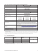
www.seagate.com Table 2 Drive Specifications DC power requirements (2-disk: 2TB model) Power dissipation (2-disk values shown) Avg (watts 25° C) Avg 5V typ amps Avg 12V amps Spinup — — 2.0A Idle2* † 4.50 0.196 0.296 Operating 6.70 0.525 0.340 Standby 0.75 0.136 0.005 Sleep 0.75 0.136 0.005 Table 3 DC power requirements (1-disk: 1TB model) Power dissipation (1-disk values shown) Avg (watts 25° C) Avg 5V typ amps Avg 12V amps Spinup — — 2.0 Idle2* † 3.36 0.152 0.
www.seagate.com Drive Specifications 2.8.4 Power-management modes The drive provides programmable power management to provide greater energy efficiency. In most systems, users can control power management through the system setup program.
www.seagate.com 2.9 Drive Specifications Environmental specifications This section provides the temperature, humidity, shock, and vibration specifications. Ambient temperature is defined as the temperature of the environment immediately surrounding the drive. Above 1000ft. (305 meters), the maximum temperature is derated linearly by 1°C every 1000 ft. Refer to Section 3.4 on page 16 for base plate measurement location. 2.9.
www.seagate.com Drive Specifications 2.9.5 Shock All shock specifications assume that the drive is mounted securely with the input shock applied at the drive mounting screws. Shock may be applied in the X, Y or Z axis. 2.9.5.1 Operating shock These drives comply with the performance levels specified in this document when subjected to a maximum operating shock of 80 Gs based on half-sine shock pulses of 2ms during read operations. Shocks should not be repeated more than two times per second.
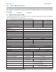
www.seagate.com Drive Specifications 2.10 Acoustics Drive acoustics are measured as overall A-weighted acoustic sound power levels (no pure tones). All measurements are consistent with ISO document 7779. Sound power measurements are taken under essentially free-field conditions over a reflecting plane. For all tests, the drive is oriented with the cover facing upward. Note Table 4 For seek mode tests, the drive is placed in seek mode only.
www.seagate.com Drive Specifications 2.13 Agency certification 2.13.1 Safety certification These products are certified to meet the requirements of UL60950-1, CSA60950-1 and EN60950 and so marked as to the certify agency. 2.13.2 Electromagnetic compatibility Hard drives that display the CE mark comply with the European Union (EU) requirements specified in the Electromagnetic Compatibility Directive (2004/108/EC) as put into place 20 July 2007.
www.seagate.com Drive Specifications If necessary, users should consult the dealer or an experienced radio/television technician for additional suggestions. Users may find helpful the following booklet prepared by the Federal Communications Commission: How to Identify and Resolve Radio-Television Interference Problems. This booklet is available from the Superintendent of Documents, U.S. Government Printing Office, Washington, DC 20402. Refer to publication number 004-000-00345-4. 2.
www.seagate.com 3.0 Configuring and Mounting the Drive Configuring and Mounting the Drive This section contains the specifications and instructions for configuring and mounting the drive. 3.1 Handling and static-discharge precautions After unpacking, and before installation, the drive may be exposed to potential handling and electrostatic discharge (ESD) hazards.
3.4 Drive mounting Users can mount the drive in any orientation using four screws in the side-mounting holes or four screws in the bottom-mounting holes. Refer to Figure 3 and Figure 4 for drive mounting dimensions. Follow these important mounting precautions when mounting the drive: • Allow a minimum clearance of 0.030 inches (0.76mm) around the entire perimeter of the drive for cooling. • Use only 6-32 UNC mounting screws. • The screws should be inserted no more than 0.150 inch (3.
www.seagate.com Configuring and Mounting the Drive Figure 4 Mounting dimensions (1TB models) Temperature Check Point Seagate Desktop SSHD Product Manual, Rev.
www.seagate.com 4.0 SATA Interface SATA Interface These drives use the industry-standard Serial ATA (SATA) interface that supports FIS data transfers. It supports ATA programmed input/output (PIO) modes 0 to 4; multiword DMA modes 0 to 2, and Ultra DMA modes 0 to 6. For detailed information about the SATA interface, refer to the “Serial ATA: High Speed Serialized AT Attachment” specification. 4.
4.3 Supported ATA commands The following table lists SATA standard commands that the drive supports. For a detailed description of the ATA commands, refer to the Serial ATA International Organization: Serial ATA Revision 3.0 (http://www.sata-io.org). See “S.M.A.R.T. commands” on page 26 for details and subcommands used in the S.M.A.R.T. implementation.
www.seagate.com Table 7 SATA Interface SATA standard commands (continued) Command name Command code (in hex) Security Set Password F1H Security Unlock F2H Seek 70H Set Features EFH Set Max Address F9H Note: Individual Set Max Address commands are identified by the value placed in the Set Max Features register as defined to the right. Address: Password: Lock: Unlock: Freeze Lock: Set Max Address Extended 37H Set Multiple Mode C6H Sleep E6H S.M.A.R.T. Disable Operations B0H / D9H S.M.
www.seagate.com SATA Interface 4.3.1 Identify Device command The Identify Device command (command code ECH) transfers information about the drive to the host following power up. The data is organized as a single 512-byte block of data, whose contents are shown in on page 19. All reserved bits or words should be set to zero. Parameters listed with an “x” are drive-specific or vary with the state of the drive.
www.seagate.com Table 8 SATA Interface Identify Device commands (continued) Word Description Value 60–61 Total number of user-addressable LBA sectors available (see Section 2.2 for related information) *Note: The maximum value allowed in this field is: 0FFFFFFFh (268,435,455 sectors, 137GB). Drives with capacities over 137GB will have 0FFFFFFFh in this field and the actual number of user-addressable LBAs specified in words 100-103.
www.seagate.com Table 8 SATA Interface Identify Device commands (continued) Word Description Value 104–107 ATA-reserved 0000H 108–111 The mandatory value of the world wide name (WWN) for the drive. NOTE: This field is valid if word 84, bit 8 is set to 1 indicating 64-bit WWN support. Each drive will have a unique value.
www.seagate.com SATA Interface 14 Shall be set to 1. 15 Shall be cleared to 0. Bit Word 88 0 Ultra DMA mode 0 is supported. 1 Ultra DMA mode 1 is supported. 2 Ultra DMA mode 2 is supported. 3 Ultra DMA mode 3 is supported. 4 Ultra DMA mode 4 is supported. 5 Ultra DMA mode 5 is supported. 6 Ultra DMA mode 6 is supported. 8 Ultra DMA mode 0 is currently active. 9 Ultra DMA mode 1 is currently active. 10 Ultra DMA mode 2 is currently active. 11 Ultra DMA mode 3 is currently active.
www.seagate.com SATA Interface 4.3.2 Set Features command This command controls the implementation of various features that the drive supports. When the drive receives this command, it sets BSY, checks the contents of the Features register, clears BSY and generates an interrupt. If the value in the register does not represent a feature that the drive supports, the command is aborted. Power-on default has the read look-ahead and write caching features enabled.
www.seagate.com SATA Interface 4.3.3 S.M.A.R.T. commands S.M.A.R.T. provides near-term failure prediction for disk drives. When S.M.A.R.T. is enabled, the drive monitors predetermined drive attributes that are susceptible to degradation over time. If self-monitoring determines that a failure is likely, S.M.A.R.T. makes a status report available to the host. Not all failures are predictable. S.M.A.R.T. predictability is limited to the attributes the drive can monitor. For more information on S.M.A.R.T.
Index A ACA 13 acceleration 11 acoustics 12 Active 9 Active mode 9 Agency certification 13 altitude 10 Ambient temperature 10 ambient temperature 6, 7 areal density 5 ATA commands 19 Australia/New Zealand Standard AS/NZ CISPR22 13 Australian Communication Authority (ACA) 13 Australian C-Tick 13 Average latency 6 Average seek time 6 B buffer 6 C cables and connectors 15 cache 6 capacity 4 CE mark 13 certification 13 Check Power Mode 19 China RoHS directive 14 compatibility 13 Conducted noise 8 Conducted RF i
N noise 8 nominal power 6 Nonoperating shock 11 Nonoperating vibration 11 O operating 7, 8 Operating power 7 Operating shock 11 Operating vibration 11 P Physical characteristics 6 point-to-point 2, 15 Power consumption 7 power dissipation 7, 8 Power modes 9 Power specifications 7 Power-management modes 9 Power-on to Ready 7 precautions 15 printed circuit board 15 programmable power management 9 prominent discrete tone 12 Q quick reference 3 R Radiated RF immunity 12 radio and television interference 13 radi
U UL60950-1 13 V voltage 7 Voltage dips, interrupts 12 Voltage tolerance 8 W weight 6 wet bulb temperature 10 width 6 Write Buffer 20 Write DMA 20 Write DMA Extended 20 Write DMA FUA Extended 20 Write DMA Without Retries 20 Write Log Extended 20 Write Multiple 20 Write Multiple Extended 20 Write Multiple FUA Extended 20 Write Sectors 20 Write Sectors Extended 20 Write Sectors Without Retries 20 Seagate Desktop SSHD Product Manual, Rev.
Seagate Technology LLC AMERICAS Seagate Technology LLC 10200 South De Anza Boulevard, Cupertino, California 95014, United States, 408-658-1000 ASIA/PACIFIC Seagate Singapore International Headquarters Pte. Ltd. 7000 Ang Mo Kio Avenue 5, Singapore 569877, 65-6485-3888 EUROPE, MIDDLE EAST AND AFRICA Seagate Technology SAS 16-18 rue du Dôme, 92100 Boulogne-Billancourt, France, 33 1-4186 10 00 Publication Number: 100726566, Rev.