® Constellation.2 v6 SATA Product Manual Standard models Self-Encrypting Drive Models ST91000640NS ST9500620NS ST9250610NS ST91000641NS ST9500621NS ST9250611NS SED FIPS 140-2 Models ST91000642NS ST9500622NS ST9250612NS 100545983, Rev.
Document Revision History Revision Date Rev. A Rev. B Rev. C Rev. D Rev. E Rev. F Rev. G 06/16/10 10/12/10 02/14/11 03/15/11 04/28/11 02/27/12 04/08/16 Sheets affected or comments Initial release. fc, 2, 15-19, 23-24 & 31. 5, 8, 10-12, 14 & 27. 13, 25, 29-30 & 33-34. fc, 2 & 5. fc, 2, 5, 28-31 & 35. 5, 9, 11, 24 & 27 © 2016 Seagate Technology LLC. All rights reserved. Publication number: 100545983, Rev.
Contents 1.0 Introduction . . . . . . . . . . . . . . . . . . . . . . . . . . . . . . . . . . . . . . . . . . . . . . . . . . . . . . . . . . . . . . . . . . . . . . . . . . . . . . . . . 6 1.1 About the Serial ATA interface . . . . . . . . . . . . . . . . . . . . . . . . . . . . . . . . . . . . . . . . . . . . . . . . . . . . . . . . . . . . . . . . 8 2.0 Drive specifications . . . . . . . . . . . . . . . . . . . . . . . . . . . . . . . . . . . . . . . . . . . . . . . . . . . . . . . . . . . . . . . . .
5.4 5.5 5.6 5.7 5.8 5.9 5.10 5.11 5.12 6.0 Drive locking . . . . . . . . . . . . . . . . . . . . . . . . . . . . . . . . . . . . . . . . . . . . . . . . . . . . . . . . . . . . . . . . . . . . . . . . . . . . . . . . Data bands . . . . . . . . . . . . . . . . . . . . . . . . . . . . . . . . . . . . . . . . . . . . . . . . . . . . . . . . . . . . . . . . . . . . . . . . . . . . . . . . . . Cryptographic erase . . . . . . . . . . . . . . . . . . . . . . . . . . . . . . . . . . . . . . . . . . . . . . . . . .
List of Figures Figure 1. Figure 2. Figure 3. Figure 4. Figure 5. Figure 6. Figure 7. Figure 8. Typical 5V/12V startup and operation current profile for 1TB models . . . . . . . . . . . . . . . . . . . . . . . . . . . . . Typical 5V/12V startup and operation current profile for 500GB models. . . . . . . . . . . . . . . . . . . . . . . . . . . Typical 5V/12V startup and operation current profile for 250GB models. . . . . . . . . . . . . . . . . . . . . . . . . . .
Seagate® Technology Support Services For information regarding online support and services, visit: http://www.seagate.com/contacts/ For information regarding Warranty Support, visit: http://www.seagate.com/support/warranty-and-replacements/ For information regarding data recovery services, visit: http://www.seagate.com/services-software/seagate-recoveryservices/recover/ For Seagate OEM, Distribution partner and reseller portals, visit: http://www.seagate.com/partners Constellation.
1.0 Introduction This manual describes the functional, mechanical and interface specifications for the following Seagate Constellation®.2 Serial ATA model drives: . Model Number Self-Encrypting Drive (SED) FIPS 140-2 Level 2 ST91000640NS No No ST91000641NS Yes No ST91000642NS Yes Yes ST9500620NS No No ST9500621NS Yes No ST9500622NS Yes Yes ST9250610NS No No ST9250611NS Yes No ST9250612NS Yes Yes Note.
These drives provide the following key features: • 7200 RPM spindle speed. • High instantaneous (burst) data-transfer rates (up to 600MB/s). • Perpendicular recording technology provides the drives with increased areal density. • State-of-the-art cache and on-the-fly error-correction algorithms. • Native Command Queueing with command ordering to increase performance in demanding applications. • Full-track multiple-sector transfer capability without local processor intervention. • Quiet operation.
1.1 About the Serial ATA interface The Serial ATA interface provides several advantages over the traditional (parallel) ATA interface. The primary advantages include: • Easy installation and configuration with true plug-and-play connectivity. It is not necessary to set any jumpers or other configuration options. • Thinner and more flexible cabling for improved enclosure airflow and ease of installation. • Scalability to higher performance levels.
2.0 Drive specifications Unless otherwise noted, all specifications are measured under ambient conditions, at 25°C, and nominal power.
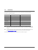
Table 1: Drive specifications summary for 1TB, 500 and 250 GB models Drive specification ST91000640NS ST91000641NS ST91000642NS ST9500620NS ST9500621NS ST9500622NS ST9250610NS ST9250611NS ST9250612NS Formatted GB (512 bytes/sector)* 1000 500 250 Guaranteed sectors 1,953,525,168 976,773,168 488,397,168 Heads 8 4 2 Discs 4 2 1 Bytes per sector 512 Default sectors per track 63 Default read/write heads 16 Default cylinders 16,383 Recording density, KBPI (Kb/in max) 1544 Track den
Drive specification ST91000640NS ST91000641NS ST91000642NS ST9500620NS ST9500621NS ST9500622NS ST9250610NS ST9250611NS ST9250612NS Drive acoustics, sound power (bels) Active 2.8 (typical) Idle** 2.2 (typical) Nonrecoverable read errors 1 sector per 1015 bits read Annualized Failure Rate (AFR) 0.62% Warranty To determine the warranty for a specific drive, use a web browser to access the following web page: http://www.seagate.
2.4 Recording and interface technology All models Interface Serial ATA (SATA) Recording method Perpendicular Recording density, KBPI (Kb/in max) 1544 Track density, KTPI (Ktracks/in avg) 270 2 Areal density (Gb/in avg) 417 Spindle speed (RPM) (± 0.2%) 7200 Internal data transfer rate (Mb/s max) 1304 Sustained data transfer rate (MB/s max) 115 I/O data-transfer rate (MB/s max) 600 2.5 Physical characteristics Weight: (maximum) 200 g (0.441 lb) 183 g (0.403 lb) 179 g (0.
2.7 Start/stop times Power-on to Ready (sec) 20 (max) Standby to Ready (sec) 13 (max) Ready to spindle stop (sec) 20 (max) 2.8 Power specifications The drive receives DC power (+5V or +12V) through a native SATA power connector. See Figure 5, page 29 on page 29. 2.8.1 Power consumption Power requirements for the drives are listed in the table on page 9. Typical power measurements are based on an average of drives tested, under nominal conditions, using 5.0V and 12.
Table 2: 1000GB drive (Standard & SED model) DC power requirements Parameter Voltage Regulation Average Idle Current Advanced Idle Current Idle1 Idle2 Idle3 Standby Average Sleep Current Maximum Start Current: DC (Peak DC) AC (Peak AC) Delayed Motor Start (DC max) Peak Operating Current (random read): Typical DC Maximum DC Maximum DC (peak) Peak Operating Current (random write): Typical DC Maximum DC Maximum DC (peak) Peak operating current (sequential read): Typical DC Maximum DC Maximum DC (peak) Peak o
500GB drive (Standard & SED model) DC power requirements Parameter Voltage Regulation Average Idle Current Advanced Idle Current Idle1 Idle2 Idle3 Standby Average Sleep Current Maximum Start Current: DC (Peak DC) AC (Peak AC) Delayed Motor Start (DC max) Peak Operating Current (random read): Typical DC Maximum DC Maximum DC (peak) Peak Operating Current (random write): Typical DC Maximum DC Maximum DC (peak) Peak operating current (sequential read): Typical DC Maximum DC Maximum DC (peak) Peak operating cu
250GB drive (Standard & SED model) DC power requirements Parameter Voltage Regulation Average Idle Current Advanced Idle Current Idle1 Idle2 Idle3 Standby Average Sleep Current Maximum Start Current: DC (Peak DC) AC (Peak AC) Delayed Motor Start (DC max) Peak Operating Current (random read): Typical DC Maximum DC Maximum DC (peak) Peak Operating Current (random write): Typical DC Maximum DC Maximum DC (peak) Peak operating current (sequential read): Typical DC Maximum DC Maximum DC (peak) Peak operating cu
2.8.1.1 Typical current profiles Figure 1. Typical 5V/12V startup and operation current profile for 1TB models Figure 2. Typical 5V/12V startup and operation current profile for 500GB models Constellation.2 Serial ATA Product Manual, Rev.
Figure 3. Typical 5V/12V startup and operation current profile for 250GB models 2.8.2 Conducted noise Noise is specified as a periodic and random distribution of frequencies covering a defined frequency. Maximum allowed noise values given below are peak-to-peak measurements and apply at the drive power connector. • +5v = 250 mV pp from 100 Hz to 20 MHz. • +12v = 450 mV pp from 100 Hz to 100 KHz. = 250 mV pp from 100 KHz to 20 MHz = 150 mV pp from 20 MHz to 80 MHz Note.
2.8.4 Power-management modes The drive provides programmable power management to provide greater energy efficiency. In most systems, you can control power management through the system setup program.
Power Condition Name Power Condition ID Description Idle_a 81H Reduced electronics Idle_b 82H Heads unloaded. Disks spinning at full RPM Idle_c 83H Heads unloaded. Disks spinning at reduced RPM Standby_z 00H Heads unloaded. Motor stopped (disks not spinning) Each power condition has a set of current, saved and default settings. Default settings are not modifiable. Default and saved settings persist across power-on resets. The current settings do not persist across power-on resets.
2.9 Environmental limits Temperature and humidity values experienced by the drive must be such that condensation does not occur on any drive part. Altitude and atmospheric pressure specifications are referenced to a standard day at 58.7°F (14.8°C). Maximum wet bulb temperature is 82°F (28°C). 2.9.1 Temperature a. Operating The drive meets the operating specifications over a 41°F to 140°F (5°C to 60°C) drive case temperature range with a maximum temperature gradient of 36°F (20°C) per hour.
2.9.3 a. Effective altitude (sea level) Operating -200 to +10,000 feet (-61 to +3,048 meters) b. Non-operating -200 to +40,000 feet (-61 to +12,210 meters) 2.9.4 Shock All shock specifications assume that the drive is mounted securely with the input shock applied at the drive mounting screws. Shock may be applied in the X, Y or Z axis. 2.9.4.
2.10 Acoustics Drive acoustics are measured as overall A-weighted acoustic sound power levels (no pure tones). All measurements are consistent with ISO document 7779. Sound power measurements are taken under essentially free-field conditions over a reflecting plane. For all tests, the drive is oriented with the cover facing upward. Note. For seek mode tests, the drive is placed in seek mode only. The number of seeks per second is defined by the following equation: (Number of seeks per second = 0.
2.12 Reliability 2.12.1 Annualized Failure Rate (AFR) and Mean Time Between Failures (MTBF) The product shall achieve an Annualized Failure Rate - AFR - of 0.62% (Mean Time Between Failures - MTBF - of 1.4 Million hrs) when operated in an environment that ensures the HDA case temperatures do not exceed 40°C. Operation at case temperatures outside the specifications in Section 2.9 may increase the product Annualized Failure Rate (decrease MTBF).
Korean RRL If these drives have the Korean Communications Commission (KCC) logo, they comply with paragraph 1 of Article 11 of the Electromagnetic Compatibility control Regulation and meet the Electromagnetic Compatibility (EMC) Framework requirements of the Radio Research Laboratory (RRL) Communications Commission, Republic of Korea. These drives have been tested and comply with the Electromagnetic Interference/Electromagnetic Susceptibility (EMI/EMS) for Class B products.
2.14 Environmental protection Seagate designs its products to meet environmental protection requirements worldwide, including regulations restricting certain chemical substances. 2.14.1 European Union Restriction of Hazardous Substances (RoHS) Directive The European Union Restriction of Hazardous Substances (RoHS) Directive, restricts the presence of chemical substances, including Lead, Cadmium, Mercury, Hexavalent Chromium, PBB and PBDE, in electronic products, effective July 2006.
2.16 Reference documents Self-Encrypting Drives Reference Manual Seagate part number: 100515636 Trusted Computing Group (TCG) Documents (apply to Self-Encrypting Drive models only) TCG Storage Architecture Core Specification, Rev. 1.0 TCG Storage Security Subsystem Class Enterprise Specification, Rev. 1.0 In case of conflict between this document and any referenced document, this document takes precedence. 2.
3.0 Configuring and mounting the drive This section contains the specifications and instructions for configuring and mounting the drive. 3.1 Handling and static-discharge precautions After unpacking, and before installation, the drive may be exposed to potential handling and electrostatic discharge (ESD) hazards.
3.2 Configuring the drive Each drive on the Serial ATA interface connects point-to-point with the Serial ATA host adapter. There is no master/ slave relationship because each drive is considered a master in a point-to-point relationship. If two drives are attached on one Serial ATA host adapter, the host operating system views the two devices as if they were both “masters” on two separate ports. Both drives behave as if they are Device 0 (master) devices.
3.4.1 Mechanical specifications Refer to Figure 6, page 30 for detailed mounting configuration dimensions. See Section 3.4, “Drive mounting. 1TB models 500GB models 250GB models Weight: (maximum) Note. 200 g (0.441 lb) 183 g (0.403 lb) 179 g (0.395 lb) These dimensions conform to the Small Form Factor Standard documented in SFF-8201 and SFF-8223 found at www.sffcommittee.org. in mm in mm in mm Figure 6. Mounting dimensions—top, side and end view Constellation.2 Serial ATA Product Manual, Rev.
3.5 Cooling Cabinet cooling must be designed by the customer so that the ambient temperature immediately surrounding the drive will not exceed temperature conditions specified in Section 2.9.1, "Temperature." The rack, cabinet, or drawer environment for the drive must provide heat removal from the electronics and head and disc assembly (HDA). You should confirm that adequate heat removal is provided using the temperature measurement guidelines described in Section 2.9.1.
4.0 About FIPS The Federal Information Processing Standard (FIPS) Publication 140-2 is a U.S. Government Computer Security Standard used to accredit cryptographic modules. It is titled 'Security Requirements for Cryptographic Modules (FIPS PUB 140-2)' and is issued by the National Institute of Standards and Technology (NIST).
5.0 About self-encrypting drives Self-encrypting drives (SEDs) offer encryption and security services for the protection of stored data, commonly known as “protection of data at rest.” These drives are compliant with the Trusted Computing Group (TCG) Enterprise Storage Specifications as detailed in Section 2.16. The Trusted Computing Group (TCG) is an organization sponsored and operated by companies in the computer, storage and digital communications industry.
5.2.3 Default password When the drive is shipped from the factory, all passwords are set to the value of MSID. This 32-byte random value can only be read by the host electronically over the interface. After receipt of the drive, it is the responsibility of the owner to use the default MSID password as the authority to change all other passwords to unique owner-specified values. 5.
3. As with a non-SED drive, the download file must pass the acceptance criteria for the drive. For example it must be applicable to the correct drive model, and have compatible revision and customer status. 5.8 Power requirements The standard drive models and the SED drive models have identical hardware, however the security and encryption portion of the drive controller ASIC is enabled and functional in the SED models.
6.0 Serial ATA (SATA) interface These drives use the industry-standard Serial ATA interface that supports FIS data transfers. It supports ATA programmed input/output (PIO) modes 0–4; multiword DMA modes 0–2, and Ultra DMA modes 0–6. For detailed information about the Serial ATA interface, refer to the “Serial ATA: High Speed Serialized AT Attachment” specification. 6.1 Hot-Plug compatibility Constellation.
6.2 Serial ATA device plug connector pin definitions Table 5 summarizes the signals on the Serial ATA interface and power connectors. Table 5: Segment Signal Serial ATA connector pin definitions Pin Function Definition S1 Ground 2nd mate S2 A+ Differential signal pair A from Phy S3 A- S4 Ground 2nd mate S5 B- Differential signal pair B from Phy S6 B+ S7 Ground 2nd mate Key and spacing separate signal and power segments Power P1 V33 3.3V power P2 V33 3.3V power P3 V33 3.
6.3 Supported ATA commands The following table lists Serial ATA standard commands that the drive supports. For a detailed description of the ATA commands, refer to the Serial ATA: High Speed Serialized AT Attachment specification. See “S.M.A.R.T. commands” on page 45.for details and subcommands used in the S.M.A.R.T. implementation.
Command name Command code (in hex) Security Disable Password F6H Security Erase Prepare F3H Security Erase Unit F4H Security Freeze F5H Security Set Password F1H Security Unlock F2H Seek 70H Set Features EFH Set Max Address F9H Note: Individual Set Max Address commands are identified by the value placed in the Set Max Features register as defined to the right. Address: Password: Lock: Unlock: Freeze Lock: Set Max Address Extended 37H Set Multiple Mode C6H Sleep E6H S.M.A.R.T.
Command name Command code (in hex) Write Multiple FUA Extended CEH Write Sectors 30H Write Sectors Without Retries 31H Write Sectors Extended 34H 6.3.1 Identify Device command The Identify Device command (command code ECH) transfers information about the drive to the host following power up. The data is organized as a single 512-byte block of data, whose contents are shown in Table 6 on page 38. All reserved bits or words should be set to zero.
Word Description Value 56 Number of current logical sectors per logical track xxxxH 57–58 Current capacity in sectors xxxxH 59 Number of sectors transferred during a Read Multiple or Write Multiple command xxxxH 60–61 Total number of user-addressable LBA sectors available (see Section 2.2 for related information) *Note: The maximum value allowed in this field is: 0FFFFFFFh (268,435,455 sectors, 137 Gbytes).
Word Description Value 100–103 Total number of user-addressable LBA sectors available (see Section 2.2 for related information). These words are required for drives that support the 48-bit addressing feature. Maximum value: 0000FFFFFFFFFFFFh. 1000GB models = 1,953,525,168 500GB models = 976,773,168 250GB models = 488,397,168 104–107 ATA-reserved 0000H 108–111 The mandatory value of the world wide name (WWN) for the drive.
1 Ultra DMA mode 1 is supported. 2 Ultra DMA mode 2 is supported. 3 Ultra DMA mode 3 is supported. 4 Ultra DMA mode 4 is supported. 5 Ultra DMA mode 5 is supported. 6 Ultra DMA mode 6 is supported. 8 Ultra DMA mode 0 is currently active. 9 Ultra DMA mode 1 is currently active. 10 Ultra DMA mode 2 is currently active. 11 Ultra DMA mode 3 is currently active. 12 Ultra DMA mode 4 is currently active. 13 Ultra DMA mode 5 is currently active. 14 Ultra DMA mode 6 is currently active.
6.3.2 Set Features command This command controls the implementation of various features that the drive supports. When the drive receives this command, it sets BSY, checks the contents of the Features register, clears BSY and generates an interrupt. If the value in the register does not represent a feature that the drive supports, the command is aborted. Power-on default has the read look-ahead and write caching features enabled.
6.3.3 S.M.A.R.T. commands S.M.A.R.T. provides near-term failure prediction for disc drives. When S.M.A.R.T. is enabled, the drive monitors predetermined drive attributes that are susceptible to degradation over time. If self-monitoring determines that a failure is likely, S.M.A.R.T. makes a status report available to the host. Not all failures are predictable. S.M.A.R.T. predictability is limited to the attributes the drive can monitor. For more information on S.M.A.R.T.
Seagate Technology LLC AMERICAS Seagate Technology LLC 10200 South De Anza Boulevard, Cupertino, California 95014, United States, 408-658-1000 ASIA/PACIFIC Seagate Singapore International Headquarters Pte. Ltd. 7000 Ang Mo Kio Avenue 5, Singapore 569877, 65-6485-3888 EUROPE, MIDDLE EAST AND AFRICA Seagate Technology SAS 16-18 rue du Dôme, 92100 Boulogne-Billancourt, France, 33 1-4186 10 00 Publication Number: 100545983, Rev.